Hi,
Is there a list of what was updated or fixed for the UIFlow2 updates?
If not, is it possible to make one?
It is excellent that it is updated occasionally, but we need to know what was updated and fixed.
Thanks.
Hi,
Is there a list of what was updated or fixed for the UIFlow2 updates?
If not, is it possible to make one?
It is excellent that it is updated occasionally, but we need to know what was updated and fixed.
Thanks.
Hi,
Just sharing my experience with using optocouplers as end-of-travel detectors using a stepper motor that drives a lead screw (that drives something else).
The optocoupler is located at the end of the travel, and when it is blocked by a small plastic sheet that travels with the lead nut, it is supposed to stop the motor.
I'm driving the stepper motor using the "stepmotor driver V1.1" module connected to a TAB5 controller, and programming with Uiflow2 V2.3.8 .
The driver module has 4 input lines to be used for feedback of the moving object location using microswitches or optocouplers, exactly what I needed.
The issue is that these lines are connected to the TAB5 through a simple I2C controller located on the driver module, and this makes it too slow to respond, so the motor is stopped after the traveler passed the optocoupler. And I'm using a pretty slow travel speed, just a few millimeters per second.
The solution for this is to use the built-in pin buttons of the esp32 of the tab5.
These pin buttons are much faster than the built-in lines of the driver module, I couldn't measure their response time, and as far as I'm concerned, they stop the motor immediately as the plastic sheet arrives at the optical slit of the optocoupler.
I was a bit surprised to see that the built-in lines in the driver module are so slow, perhaps using a faster than the Uiflow2 programing language can squeeze faster response times from them, but I suspect it is not the case, since the delay is due to the extra serial communication between the esp32 and the i2c controller on the driver module.
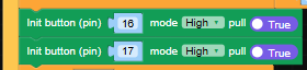
See attached photos for the code using pin buttons:
Define pin buttons on setup:
Call for update in main loop and define operations when called:
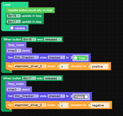
In my case I use two optocouplers, one for each end of the travel.
Their callbacks stop the motor and reverse the motor direction.
@MortenComadan Hi,
If your OBD2 scanner can work with BLE protocols, you can take a look at the following look for some guidance:
https://uiflow-micropython.readthedocs.io/en/latest/system/m5ble.html
There are examples there and some basic info on the higher level functions to handle BLE.
@BR123456
Problem solved. See:
https://community.m5stack.com/post/30264
@Rusticus42 Hi,
You didn't find because there is no formal way to do that.
This is in order to protect your hardware from conflicts.
If you switch hardware and stay with the previous code, pin allocations, I2C addresses etc. will probably be wrong and will have conflicts that might cause damage.
What you can do if you feel responsible enough is to export your project to a file on your hard disk, open it in a text editor and change the "type" parameter to your new hardware type (keep the name in lower caps).
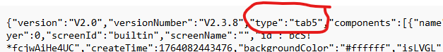
In this example it is tab5. If you change for example to Core2, replace the "tab5" by "core2", then save the file and import it from the Uiflow2 ide.
Again, you should go thoroughly over your code before running the code and fix all hardware related commands.
Do this at your own risk!
@kuriko said in TAB5 I2C issues using UIflow2:
@BR123456
The default internal I2C scanner of Tab5 in UiFlow2 has bug, we are now fixing it!
I've just found a hack for this bug.
One has to define the I2C port pins before initializing the stepmotor module, as shown in the image.
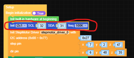
The module works fine now.
@kuriko Hi Kuriko,
Any estimation when this bug will be fixed?
Is there a way to bypass this bug? I do need to operate the ""Stepmotor driver V1.1"" with the TAB5.
Hi,
I'm controlling a stepper motor with the Core2 with a Stepper motor driver V1.1 attached to it.
I'm managing to control the motor using Uiflow2 V2.3.8, but couldn't find a way to move the motor a predefined number of steps. It is only possible to start or stop it.
Is there a way to move it number of steps with Uiflow2, or adding some python code manually?
Or perhaps it is possible to move the motor by sending pulses on it's Step pin?
Thanks
@felmue Hi Felix,
I will try your suggestion, thanks!
Boaz
Hi,
I'm trying to handle some stepper motors using the "stepmotor driver module V1.1" on the UIflow 2.3.8 IDE.
I'm connecting the module to the M-Bus at the back of the TAB5, but the TAB5 won't recognize it and won't show it on the I2C list using the default scanner that comes with the official TAB5 UIflow2 firmware.
It does recognize an 8Servo unit when connected to the I2C Port.A at the side of the TAB5.
I've tried also connecting a 4in8out module on the TAB5 M-Bus, but it is not recognized as well.
The 2 modules (stepmotoer driver and 4in8out ) do work when connected to a Core2 M-Bus, so these units are OK.
It's either my TAB5 arrived faulty, or there is an issue with the I2C on the M-Bus of the TAB5, at least when using UIFlow2 IDE.
Any suggestions?
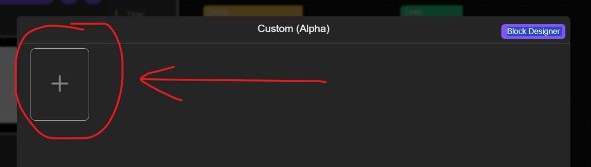
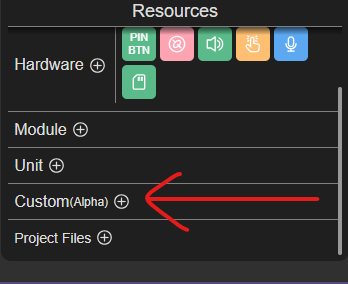
@dlhawley I never tried making custom blocks, but i assume that after saving them you have to add them to your custom block library using the big + button.
You can ask one of the AI chats, I use Gemini, in most cases it knows UiFlow2 pretty well.
Hi,
I have tried using the USB-A port on the TAB5 as a host for sending serial commands to a 3D printer, but it seems there are no supporting blocks in UiFlow2 for accessing the USB ports.
Did I miss something?
Will there be support for this in the future?
Thanks.
@DaveAstator If you're still interested in this topic, you now have the "Custom" Block designer.
@ajb2k3 I'm not so sure. It is a fairly large request, and probably needs funding. It needs to be initiated by the suppliers, only then it will be directed to the micropython writers.
@felmue Thanks.
I thought of doing this, but it is a kind of a patch, not a fix. The whole advantage of having callbacks functions that perform distinct operations outside of the main loop is almost eliminated by doing this. The main loop need to be as clean as possible, otherwise very quickly it becomes very long and messy.
Functions outside the main loop should be working properly, unless there is a fundamental reason why they cant access the display libraries properly.
It looks like a fundamental bug in how the firmware on the TAB5 treats the external functions.
This is a big one, but will make lot's of users very happy.
Add the option to compile the micropython code generated by the UIFlow2 IDE and load it to the controller (like in the Arduino IDE).
Development will be done using the current mode of using the firmware on the controller to run the micropython code (as an interpreter). This makes the development very convenient, user friendly and quick.
After the development is done, the user can compile the code to binary code and load it on the controller for best performance.
Code acceleration options such as add a @micropython.native decorator before critical functions in order to boost their performance.
Perhaps add a simple "Real Time" library of blocks including some low level blocks.