@hanktttop OK. I'm wading into this discussion without having a Cardputer!
My other ESP32-S3 and M5Stack Atom S3 and several StampS3s all work very well in my Arduino IDE environment. I also have a bunch of S3 products from a manufacturer whose name cannot be said. (coughs into hand...T-Display S3).
So I am familiar with this S3 series on a M1 iMac.
My iMac has two Thunderbolt ports and two USB ports. I used the USB ports just fine for M5Stack-pre-S3-models, but the S3 models wont even power up on USB, they need the Thunderbolt outputs.
So, get to the point, teastain.
Connection is VERY fussy and unpredictable with S3.
All of the M5Stack S3 products that I have seen have both of the necessary buttons available. The Cardputer even has them at the front(!) no need to remove the S3 or peel back the sticker on Cardputer. (in fact DO NOT remove the S3 with Cardputer!)
The GO button is actually GPIO 0 and is called 'boot'.
The 'rst' button is otherwise called 'EN' which cuts power to the core when pushed and resets when released.
Method 1 unplug the Cardputer from the USB, press and hold G0 (on the left side of the Cardputer, plug back in and release G0.
Method 2 while plugged in press and hold G0, press 'rst' on the right side, release 'rst', then release G0.
In both cases if your sketch does not boot up and run, it is recommended to unplug it and plug it back in to boot.
teastain
@teastain
Retired Industrial Robotics interface designer, bon vivant, raconteur, maker.
Best posts made by teastain
-
RE: Cardputer COM Not Working
-
RE: Connecting M5stack to PCB with header and GPIO capacity.
@mtylerjr The Core Basic has 15 GPIO peripherally arranged in the battery base, as well as generous grounds and voltage options.
-
RE: Looking for kind souls to adopt this aged brain and eyes.
@ajb2k3 I really like the idea of REPL !
MY(!) aging brain is resisting learning a new programming language.
In the (late) 70's I programmed in machine code and felt C was a "high level language".
I will investigate Python, could be fun!
Cheers to all.
-
RE: How to change the I2C address of EXT.IO2
@felmue "For testing integrity" I'm using the github EXT.IO Zip download and running the DIGITAL_INPUT_OUTPUT example right from there and then later from my Arduino directory, after checking that both Libraries M5Stack And EXT_IO are up to date.
Note, stubbornly I am using Arduino 1.8.19.
The Example would not run until I added Wire.begin(21, 22); delay(1000);
Seriously. I take it out and the sketch throws errors.
I am also disappointed that setPinMode "came and went".
I am becoming discouraged with M5Stack, unfortunately. -
RE: UnitCamS3 Trouble programming in Arduino IDE and getting 2mp image
@ajb2k3 Sure, here it is:
Here is the full example for all ESP32s using the OV2640 camera in Arduino IDE
(in the IDE board selection choose M5Stack UnitCamS3)
Remember to edit the .ino file to include your WiFi credentials!The full sketch is here:
https://github.com/espressif/arduino-esp32/tree/cf448906b3836fbe9368934713b697469254c62f/libraries/ESP32/examples/Camera/CameraWebServerYou can choose CAMERA_MODEL_ESP_EYE, and apply a little tweak in camera_pins.h like this:
https://github.com/m5stack/UnitCamS3-UserDemo/blob/main/firmware/src/hal/cam/camera_pins.h#L21Also in the library used in your sketch
app_httpd.cpp
I had to change Line 77 from ('1" enabled) to ('0' not enabled )#define CONFIG_LED_ILLUMINATOR_ENABLED 0
Successful upload serial output reads like this:
20:48:24.952 -> E (516) esp_core_dump_flash: No core dump partition found! 20:48:24.952 -> 20:48:24.952 -> ...... 20:48:24.952 -> WiFi connected 20:48:24.952 -> Camera Ready! Use 'http://192.168.0.37' to connect
-
RE: High Level Question regarding M5Stamp and Core2
Hi, I have a Core Basic HVAC program communicating with two Stamps using ESP_NOW and they are physically close, but the idea was to not run messy cables! The ESP_NOW is peer to peer WiFi, but no login to the internet or even the WiFi router.
One Stamp reads the HVAC vent temperature and reports to the Core, which in turn calculates the damper vane angle and transmits that back to the very same Stamp connected to a 180 servo motor.
The other Stamp just operates one or two small under desk heaters as required, by the Core.
Hope this helps.
Terry -
RE: M5cardputer com is reading it as DFROBOT-Beetle
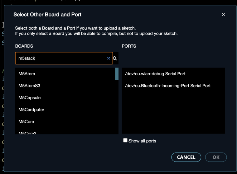
@coolman626 This is sadly a confusing aspect of Arduino IDE V2...a "feature" that guesses your board as a "convenience" and it's always wrong.
In the search box start typing M5Stack until you see your board!
Really no big deal!
-Terry -
RE: The other M5Dial connectors...
@lordryck They are called Grove and are the standard for most M5Stack products.
https://shop.m5stack.com/pages/search-results-page?q=grove cable
Also used by Seeed products.
They're JST connectors type 'HY2.0-4P'.
-
RE: m5stack cardputer doesn't turn on.
@sl4sh00 To put it into 'download' mode you can do as @robski suggested or:
Press and hold the G0 Boot button...while holding it in, press and release the reset button, THEN release the G0 Boot.
While doing this you can check the connection status in whatever burner app you are using.
Please tell us if you can see the connection status AT ALL, this would be helpful in solving your problem.
Latest posts made by teastain
-
RE: REQUEST FAILED CREATE NEW PROJECT
@Rango We are experiencing Internet outages here in Canada in the last few days due to Solar Flares. On and off, some sites worse than others and I think some parts of the world experience it differently.
Had 'Interac' difficulties trying to pay for gas!
This may be what you are experiencing.
(Ironically I am working on a WiFi and Internet Trouble detecting, cute little device, based on a Stamps3 and a matching sized uOLED (from Sparkfun)) -
RE: How to extract the current Flash and EEPROM data from M5Stack fire to Windows11 file ?
@RuriObb You cannot extract the source code from an ESP32 except a raw bin file.
But this is the example Arduino IDE source code (C, C++) on Github:
https://github.com/m5stack/M5-ProductExampleCodes/tree/master/Application/Bala2 -
RE: thermometer with a 1-wire probe
@ddhard Sounds like a great starter project, good luck!
Are you planning on using Python, UIFlow or Arduino IDE ?
Plenty of good IOT examples on The Internet.
What controller?
See here:
https://shop.m5stack.com/products/lan-module-w5500-with-poe-v12
or here
https://shop.m5stack.com/products/esp32-ethernet-unit-with-poe -
RE: Need Module with I/O for connections...
@SirMichael They core basic has a lot of pins in the battery base, did you look at it? (about 15 GPIO)
https://docs.m5stack.com/en/core/basic_v2.7
Also you may can add the PaHub or PbHub to expand.
https://docs.m5stack.com/en/unit/pbhub -
RE: Power needed
@leaguen said in Power needed:
The HC-SR501 is an old Arduino era sensor designed for 5V. Many people use it with an ESP32 3.3V with success.
But yeah, putting 5V to either 5V pin will power the ESP32 @ 3.3V and 3.3V will appear at the side 3.3V pin. And 5V will appear on the Grove 5V pin.
Very clever design. -
RE: Power needed
@leaguen Great, so you are supplying it with 3.3V.
If you supply 5V through the 5V connector on the left side, 5V will also be at the bottom 'Grove' connector...and the 5V will be stepped down to 3.3 for the Stamp ESP32 ckt...and 3.3 will be available at the 3.3v pin on the other side.
Win-win.
Do you have a part number for the IR sensor?
I would like to check it out, maybe runs on 3.3V? (Despite the rating) -
RE: Power needed
@leaguen How do you power the Stamp now? If you input 5V to either 5V pin, the Stamp will get 3.3V and the other pin will be 5V.
The Docs are here:
https://docs.m5stack.com/en/core/stamp_pico
What sensor needs 5V? (just curious as I am almost exclusively 3.3V now) -
RE: Power needed
@leaguen OK! Curious thing about the Stamp pico is that 3.3V in from the programmer device is all that is available at the ""5V"" pins!
There is no Boost regulator on this one.
-
RE: Power needed
@leaguen You can solder directly to the Stamp Pico or install a Grove connector, I think it came with one?