@Danieldsouza
I prefer to use KiCAD for schematic and PCB design.
- The software is open source
- It runs on Windows, Linux, Mac
- there is a strong community
- there is a ton of libraries for thousands of components
- some part distributor and assembling factories provide their own library or allow symbol and footprint download
- making your own symbols and footprints is very easy
- design rule checking
I am not an advanced user but managed to make a 4-layer PCB after watching a few tutorial videos.
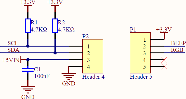
Independend of the EDA Tool make sure you avoid the common tripping hazard like missing blocking caps or unwanted ground loops.