Also mine now up and running !
thanks to M5 stack support
hope it will remain stable
point closed
Davide

Also mine now up and running !
thanks to M5 stack support
hope it will remain stable
point closed
Davide

Just resume this request
any chance to get STEP or even STL file of the “core module” ?
I’m developing my custom expansion board and beside using the cad model available for the proto as base line I would like to make a full rendering and project design including core
mechanical drawing and final object rendering is quite tricky without a precise CAD model of core
thanks
Davide
Hi
I'm usuing the scale unit (HX711 based ) with M5stick C core in UiFlow
is there any way to perform the calibration procedure ?
the scale program works fine but HX711 need a pre-calibration procedure with well know weight to determine the calibration factor to be used in the conversion
I see only mehtod to "get weight" and "tare to zero"
don't know how to modify the calibration factor..
thanks
Davide
Hi guys
I would like to use ubiquitous DS18B20 temp sensors (dallas 1-wire) connecting directly to the M5stack core or M5 stickC core I2C port
Sensor works perfectly with power supply ranging from 3 to 5.5v, on the grove I2C connector I can use 5V power but the SCL/SDA lines (will use one to read the sensor) connected to the ESP32 are 3.3v logic
Any ideas on how to manage such a situation in general? How to manage 3.3v external logic with 5V power supply from the expansion port ?
possible option I see..
-partition resistor
-clamp diode (TVS, Zener)
-level shifter
-3.3v LDO on the external circuit
any suggestion is appreciated
br
Davide
Hi
I’m facing a strange issue with my M5stack core implementation
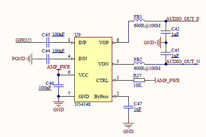
When I generate a tone used to fire a sound alarm, a continuous “beep”, in my control process this causes a reboot of the M5stack core
I drive the GPIO25 with PWM signal (just need a beep)
Seems something related to the power used by the class D amplifier NS4148 that sink too much current from EA3036 buck converter and this cause ESP32 reboot

notice that I power the M5stack core via HLK-PM01 Enclosed AC DC Converter 1 Output 5V 600mA
does any one experience something similar ?
Any idea / suggestions on how to drive the audio amplifier properly to reduce power consumption ?
Thanks
Davide!
Thanks Felix I see the version table !
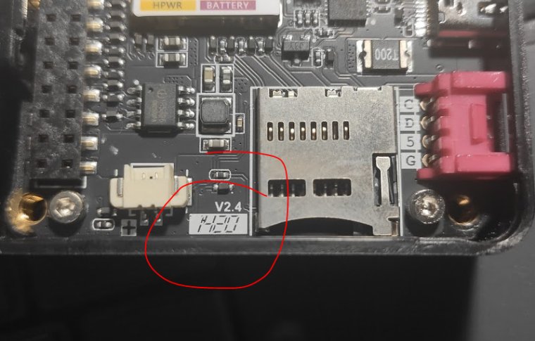
my PCB is marked v2.4 what is the correct mapping on that table ?

Davide
Hi
what are the main HW /engineering difference between the Old core version (2.4) and the new one V2.6?
thanks
Davide
Hi
I'm usuing the scale unit (HX711 based ) with M5stick C core in UiFlow
is there any way to perform the calibration procedure ?
the scale program works fine but HX711 need a pre-calibration procedure with well know weight to determine the calibration factor to be used in the conversion
I see only mehtod to "get weight" and "tare to zero"
don't know how to modify the calibration factor..
thanks
Davide
@robalstona said in Ui Flow upload made persistent?:
I don't know exactly what you want to get.
Exactly what you describe so run the python script with no UIflow boot
Like when you load a sketch vi arduino IDE
is there any guide to load directly the python script and how to edit the boot.py?
Davide
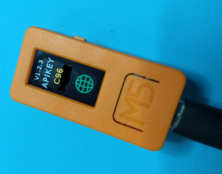
Is there any way beside loading permanently the code and lunch it at startup to inhibit also the UIflow boot and network scan ?
So want just tu run the pure application code without the possibility to connecte to wifi and connect again to the online IDE via API KEY
thanks
Davide
Any chance to get the correct schematic of M5stick C
I was thinking that the one on Github was correct but is the old M5stick
I think it should be very beneficial to have he complete schematic and not just a block diagram (by the way not precise..ie RTC missing..)
At the end of the day M5stick C is a proto board (indeed very nice) done for makers and developers...people who want to exploit potential from your product and not having access to the schema seems a sort of contradiction
I hope you can release the schema and off course I respect anyway your philosophy
Davide
Hi
I have some doubts and inconsistency in the documentation related to M5stick C push button mapping
In the documentation we have
https://docs.m5stack.com/#/en/core/m5stickc
BUTTON A GPIO 37
BUTTON B GPIO 39
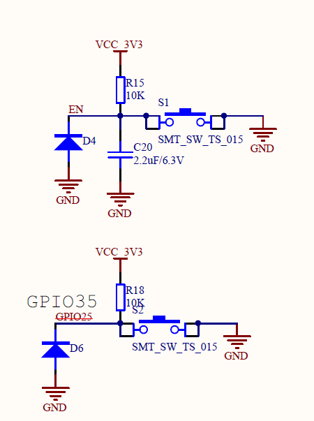
If I check the schematic I don’t see the mapping at all
https://github.com/m5stack/M5-Schematic/tree/master/Core
In the ESP Core schema there are no GPIO37 mapping on ESP32
In the UART schema I found two buttons: one connected to GPIO 35 , the other one to EN net so PIN 5 of IP5306 / PIN3 of ESP32

Really confuse
More over the left button, the power ON/OFF button where is connected is the one connected to IP5306 ?
Can someone provide clarification and provide a correct schematic ?
thks
Davide
I share m5 support answer on the topic
"UART0 is a specifically assigned for log print, it is encapsulated by ESP32 at lower layer. It will print the system log automatically and seems like we users are not permitted to shut it down, so we don’t recommend users to use UART0 as a normal UART series port, it will interrupt you communication. That why we connect it with CP2104."
to me it's clear the usage of UART0 ..less cleare why this two GPIO are routed to the M5bus since can't be used
I will use UART2 for my custom project with this assignment GPIO34=RX GPIO17=TX
Davide