Analog-style digital voltage meter by tomorrow56

Original article link
Introduction
I introduce a simple analog style digital tester (voltage meter, DVM) created using the compact development module "M5Stack" integrated LCD equipped with ESP32 manufactured by Espressif systems.
M5Stack Overview
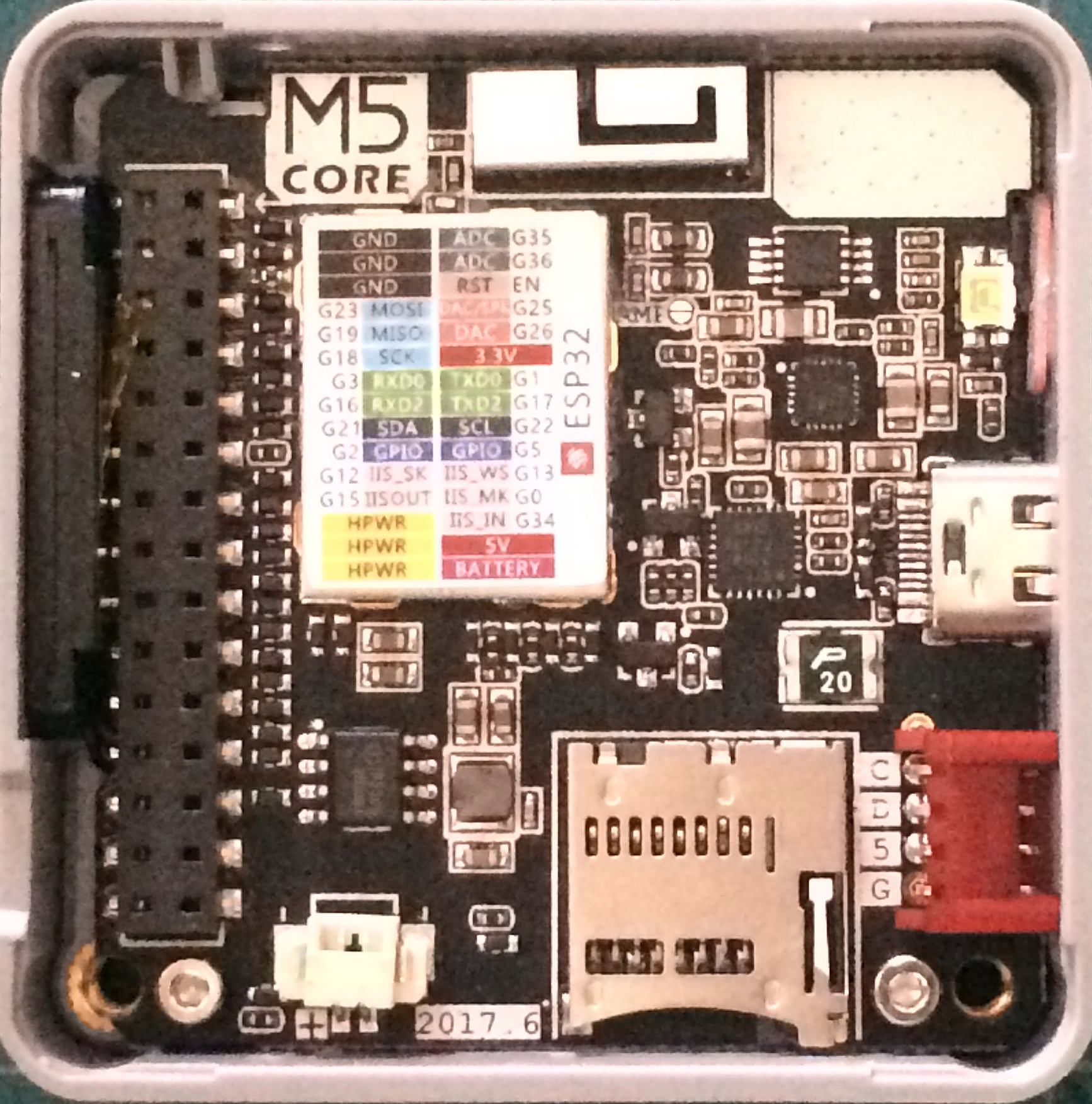
M5Stack is a compact development module that includes a color LCD display, microSD card slot, and speakers in a 5.4cm x 5.4cm chassis. The SoC "ESP32" installed supports Wi-Fi (2.4 GHz band) and BLE, enabling the development of applications using an LCD display and wireless communication.
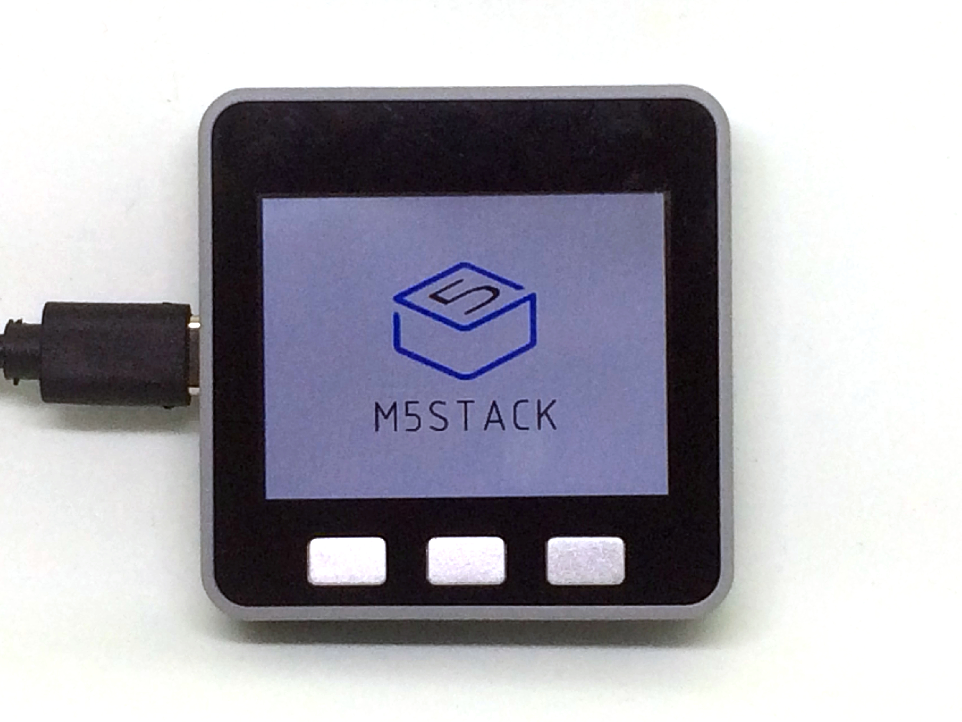
The back side has its own expansion connector (M-BUS), and it can extend the function by "Stacking" a dedicated module.
My Work
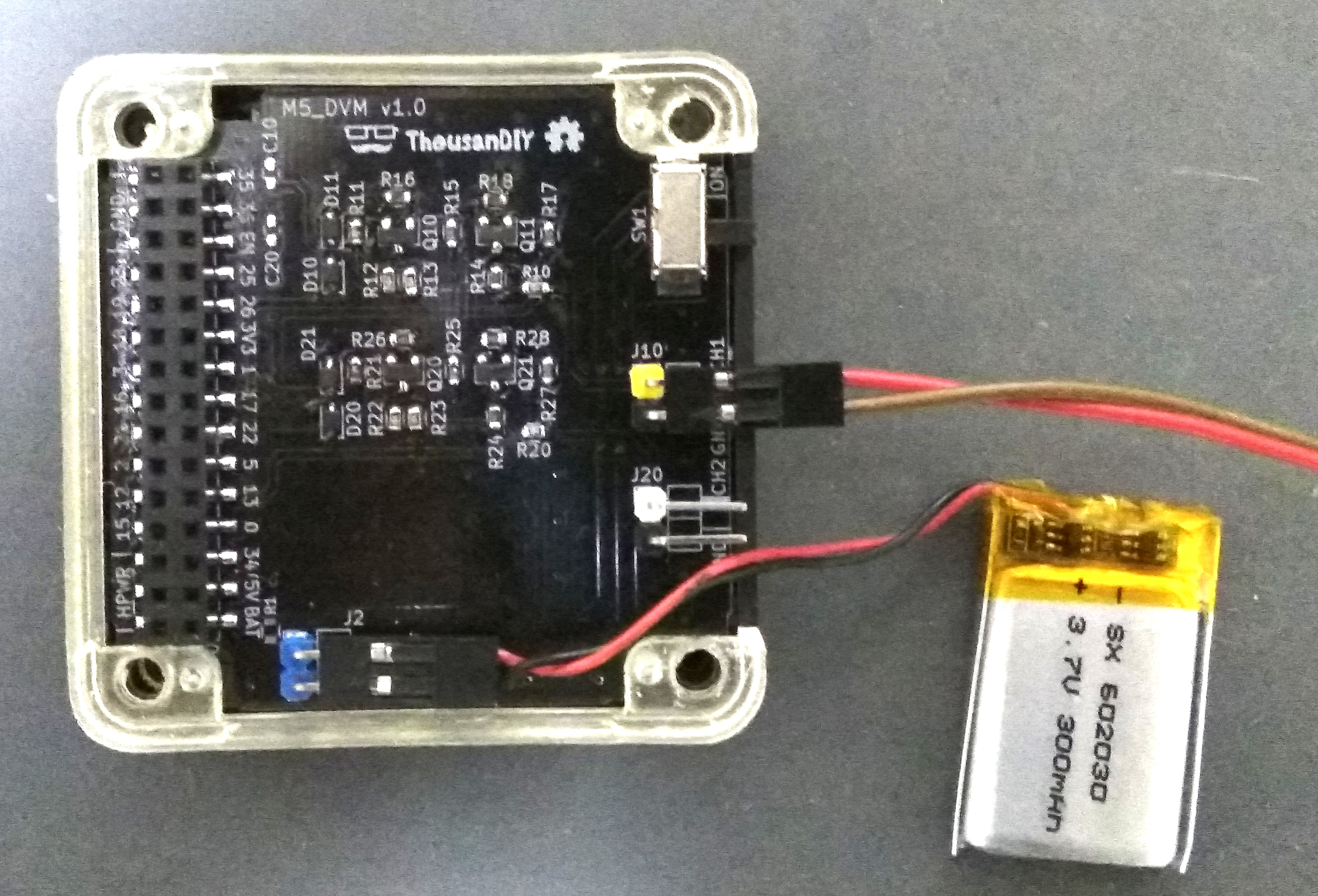
The following picture is the operation screen and the expansion board of the DVM.

Targeted features
The main functions are as follows.
- Analog style meter with digital value
- Measurement range: 0.15V to 20V (automatic range switching)
- Overvoltage / Reverse voltage protection
- Hold function of measured value by HOLD button
Create hardware
As hardware, I created an expansion board connected to "M-BUS" for voltage input and range switching. There are two inputs, considering the case of using two channels of ADC with an oscilloscope etc.
In general, priority was given to simple realization with parts that can be purchased normally in Akihabara. The following is a circuit diagram of the expansion board.
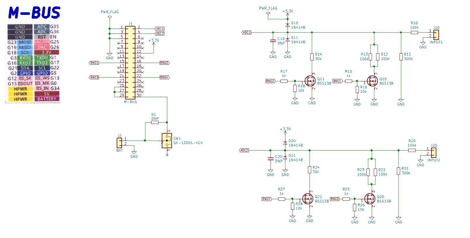
In the circuit diagram, a connector is added to attach the LiPo battery to the BAT pin in consideration of replacing the base module. No additional LiPo battery is required when using stacked base modules.
Hardware Specification
The target specifications were as follows when creating the hardware part.
- Input impedance: 100kΩ or more
- Voltage measurement range: Up to 20 V
- Automatic range switching
- Over voltage / Reverse voltage protection function
Input impedance determination
In order to minimize the voltage drop of the measurement object by connecting this unit, the input impedance should be 100kΩ or more.
Specifically, 100kΩ is inserted in series to the input. The input range is simply adjusted by switching the resistor connected in parallel between the AD converter input and GND.
Voltage measurement range and auto range switching
Since the AD converter input of M5Stack does not have very good linearity, I decided each resistance value to use in the range up to 3V. The following figure shows the measurement range, the ratio of the input value to the A / D converter, and the value of the dividing resistance required for it. Assuming that the measurement range is three steps (4 V / 10 V / 20 V), the combined resistance value is 300 kΩ / 50 kΩ / 30 kΩ.

Auto range switching was realized by switching the dividing resistors with FET. The FET uses BSS138 (Nch MOSFET). As the ON resistance is approximately 8Ω, which is sufficiently smaller than the division resistance value, the influence on the measured value is negligible.
BSS 138 can be purchased from Akizuki Electronic Commerce.
http://akizukidenshi.com/catalog/g/gI-04232/
Overvoltage / Reverse voltage protection function
A protection diode is added between the input and 3.3V / GND to protect the overvoltage and reverse voltage to the AD converter input. Initially we experimented with a 3.3V zener diode, but because the leakage current was large and the voltage drop at the series resistance affected the measured value, we constructed a protection circuit using two switching diodes.
The diode uses 1N4148. This can also be purchased from Akizuki e-commerce.
http://akizukidenshi.com/catalog/g/gI-07084/
Deciding which M-BUS pin to use
The M-BUS pins used for AD converter input and range switching have been determined as follows. I use only ch1 this time.
- AD converter input (ch1): Pin 35
- Range switching 1: Pin 16
- Range switching 2: Pin 17
- AD converter input (ch2): Pin 36
- Range switching 3: 12th pin
- Range switching 4: Pin 13
As a point of IO selection, try to avoid the following pins as much as possible.
- Pins used in M5Stack internal devices
- Pin for mode setting at startup (Strapping Pin)
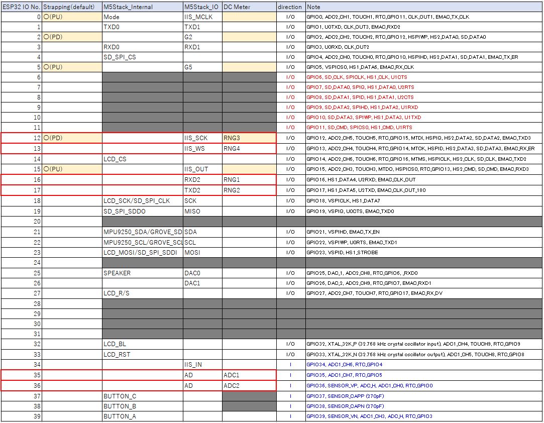
Especially for "Pin for mode setting at startup", if the polarity of pull-up / pull-down at startup is incorrect, M5Stack itself will not start up. There are a large number of pins used for internal devices, and the number of freely usable pins is limited, so be careful when creating an expansion board.
Although the #12 pin used for range switching 3 of ch2 this time is Strapping Pin, it was determined that there is no problem in circuit configuration because it is the default Pull Down.
Create software
Development environment
Use Arduino IDE as a development environment. To program with Arduino IDE, it is necessary to add "M5Stack library" to the "Arduino Core for the ESP32" environment. The official documentation for building the Arduino IDE environment for M5Stack is available from M5Stack.
https://docs.m5stack.com/#/en/quick_start/m5core/m5stack_core_get_started_Arduino_Windows
Software specification
The target specifications were as follows when creating software.
- Display voltage value with "needle" on the screen of analog meter style
- Display the measured digital value together on the screen
- Auto range switching has hysteresis
- Hold function of measured value by pressing "HOLD" button
The sketches created this time and the necessary design data are available on github.
https://github.com/tomorrow56/M5Stack_DVM
Sketch based
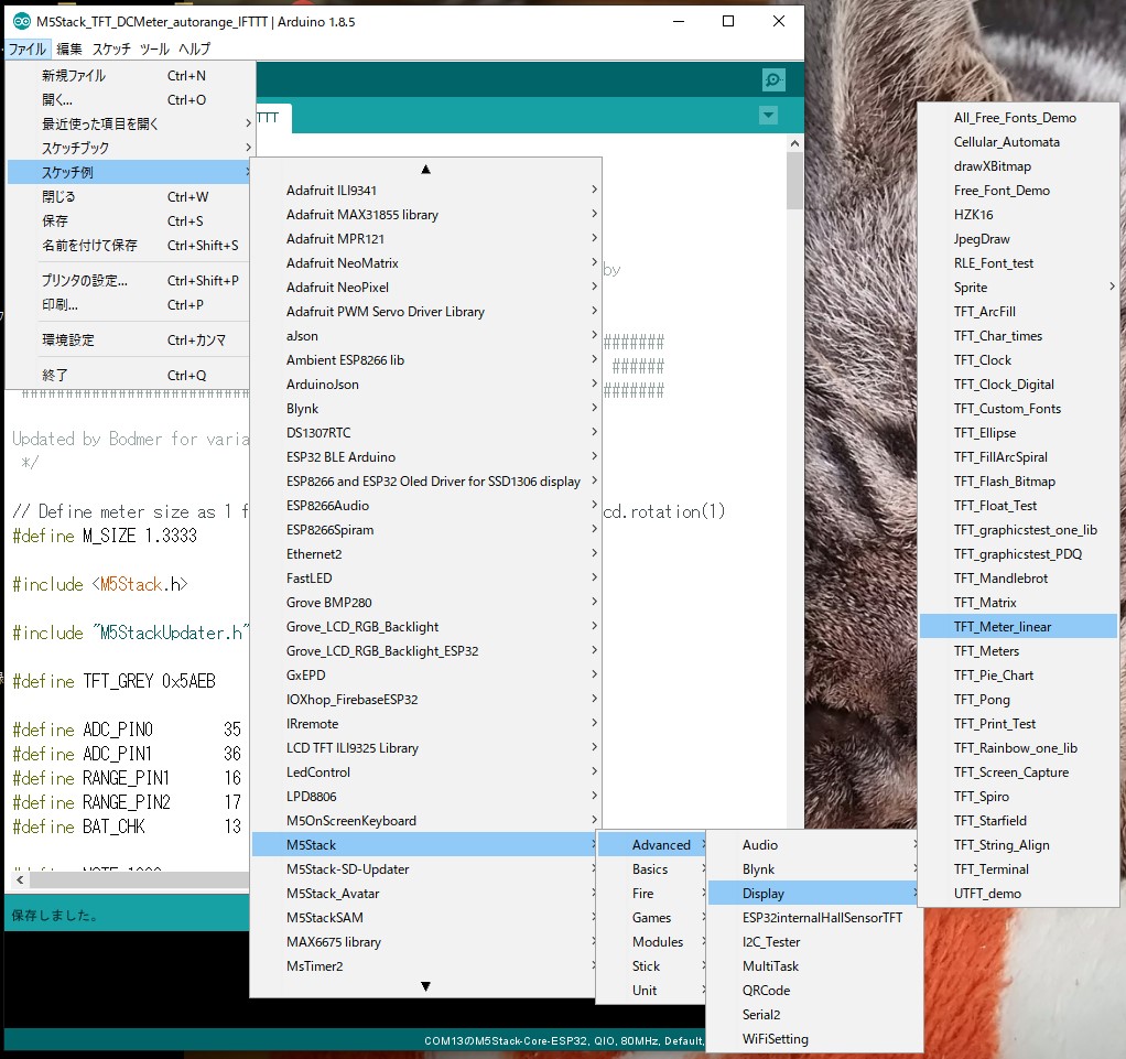
The analog meter style display is based on "TFT_Meter_linear.ino" included in the M5Stack example.
"TFT_Meter_linear.ino" is located below the example sketch, so load it and save it with an arbitrary name in "Save As".
[File]-> [Example]-> [M5 Stack-> [Advanced]-> [Display]-> [TFT_Meter_linear]
The following describes the main modification points of the created sketch.
modification of screen display part
Meter title modification
Since the sketch of the base is "hydrometer", search for "% RH" and rewrite it as "Vdc". (3 places)
Modify analogMeter() function
Modify the analogMeter() function that displays the analog meter screen as follows.
Disable Zone limit color
Comment out the following, as the color coding has little meaning in voltage display.
/*
// Green zone limits
if (i >= 0 && i < 25) {
    M5.Lcd.fillTriangle(x0, y0, x1, y1, x2, y2, TFT_GREEN);
    M5.Lcd.fillTriangle(x1, y1, x2, y2, x3, y3, TFT_GREEN);
}

// Orange zone limits
if (i >= 25 && i < 50) {
    M5.Lcd.fillTriangle(x0, y0, x1, y1, x2, y2, TFT_ORANGE);
    M5.Lcd.fillTriangle(x1, y1, x2, y2, x3, y3, TFT_ORANGE);
}
*/
Range switching support
Since the label of the meter is fixed, this is used as a variable so that it can be switched according to the measurement range.
/*
case -2: M5.Lcd.drawCentreString("0", x0, y0 - 12, 2); break;
case -1: M5.Lcd.drawCentreString("1", x0, y0 - 9, 2); break;
case 0: M5.Lcd.drawCentreString("2", x0, y0 - 7, 2); break;
case 1: M5.Lcd.drawCentreString("3", x0, y0 - 9, 2); break;
case 2: M5.Lcd.drawCentreString("4", x0, y0 - 12, 2); break;
*/

case -2: M5.Lcd.drawCentreString(MeterLabel[0], x0, y0 - 12, 2); break;
case -1: M5.Lcd.drawCentreString(MeterLabel[1], x0, y0 - 9, 2); break;
case 0: M5.Lcd.drawCentreString(MeterLabel[2], x0, y0 - 7, 2); break;
case 1: M5.Lcd.drawCentreString(MeterLabel[3], x0, y0 - 9, 2); break;
case 2: M5.Lcd.drawCentreString(MeterLabel[4], x0, y0 - 12, 2); break;
Modify plotNeedle() function
Since the digital display value in the plotNeedle() function that draws the "Needle" of the analog meter needs to be changed according to the range, you will comment out and move to the loop() function here.
//  M5.Lcd.setTextColor(TFT_BLACK, TFT_WHITE);
//  char buf[8]; dtostrf(value, 4, 0, buf);
//  M5.Lcd.drawRightString(buf, M_SIZE*40, M_SIZE*(119 - 20), 2);
Modify the setup() function
Added specification of pin mode and initial value
pinMode(RANGE_PIN1, OUTPUT);
pinMode(RANGE_PIN2, OUTPUT);
digitalWrite(RANGE_PIN1, LOW);
digitalWrite(RANGE_PIN2, LOW);
Add "HOLD" label to A button
M5.Lcd.setTextColor(TFT_GREEN, TFT_BLACK);
M5.Lcd.drawCentreString("HOLD", 70, 220, 2);
Modify loop() function
Implementation of "HOLD" function by A button
Press the A button to switch the HOLD variable false / true, and when HOLD == true, stop updating the read value from the AD converter and hold the display value (HOLD).
if(Hold == false){
    Vread = analogRead(ADC_PIN0);
}
~~~~Omission~~~~
M5.update();
if (M5.BtnA.wasPressed()) {
    Hold  = !Hold;
    if(Hold == true){
        M5.Lcd.setTextColor(TFT_YELLOW, TFT_BLACK);
    }else{
        M5.Lcd.setTextColor(TFT_BLACK, TFT_BLACK);
    }
    M5.Lcd.drawCentreString("DATA HOLDING...", 160, 180, 4);
}
Correction of AD converter input voltage and AD conversion value
The measured characteristics of the input voltage value and AD conversion value of the ESP32's AD converter mounted on M5Stack are shown below.
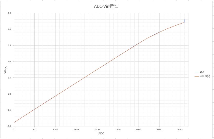
The following characteristics can be read from this graph.
- Can not measure less than 0.11V at AD converter input (out of effective range)
- When the input voltage is increased, the linearity is deteriorated halfway
This time, the following measures were taken to simplify the process.
- Read value less than 0.11V at AD converter input is invalid (0)
- For linearity, divide the input range into several and approximate with a straight line
Specifically, the AD conversion value (Vread) read in the loop() function is converted to the AD converter input voltage (Vdc) with the following code. Even with a simple approximation, it could be measured with an accuracy of about +/- 10mV by measurement.
if(Vread < 5){
    Vdc = 0;
}else if(Vread <= 1084){
    Vdc = 0.11 + (0.89 / 1084) * Vread;
}else if(Vread <= 2303){
    Vdc = 1.0 + (1.0 / (2303 - 1084)) * (Vread - 1084);
}else if(Vread <= 3179){
    Vdc = 2.0 + (0.7 / (3179 - 2303)) * (Vread - 2303);
}else if(Vread <= 3659){
    Vdc = 2.7 + (0.3 / (3659 - 3179)) * (Vread - 3179);
}else if(Vread <= 4071){
    Vdc = 3.0 + (0.2 / (4071 - 3659)) * (Vread - 3659);
}else{
    Vdc = 3.2;
}
Automatic range switching function
The value of the RANGE variable is automatically changed according to the input voltage of the AD converter, and the RangeChange flag is set to true. It has a simple hysteresis characteristic so that the voltage near the boundary of range switching does not flutter.
if(Vdc > 3.0 && RANGE < 2){
    RANGE = RANGE + 1;
    RangeChange = true;
}
if(Vdc < 0.75 && RANGE > 0){
    RANGE = RANGE - 1;
    RangeChange = true;
}
Switches between the split resistance value and the screen display label / input range according to the value of the RANGE variable.
switch (RANGE){
    case 0:
        PARA_RES = TERM_RES1;
        MeterLabel[0] = "0";
        MeterLabel[1] = "1";
        MeterLabel[2] = "2";
        MeterLabel[3] = "3";
        MeterLabel[4] = "4";
        digitalWrite(RANGE_PIN1, LOW);
        digitalWrite(RANGE_PIN1, LOW);
        VdcDisp = VdcCalc * (100 / 4);
        break;
    case 1:
        PARA_RES = 1/ ((1 / TERM_RES1) + (1 / TERM_RES2));
        MeterLabel[0] = "0";
        MeterLabel[1] = "2.5";
        MeterLabel[2] = "5";
        MeterLabel[3] = "7.5";
        MeterLabel[4] = "10";
        digitalWrite(RANGE_PIN1, HIGH);
        digitalWrite(RANGE_PIN2, LOW);
        VdcDisp = VdcCalc * (100 / 10);
        break;
    case 2:
        PARA_RES = 1/ ((1 / TERM_RES1) + (1 / TERM_RES2) + (1 / TERM_RES3));
        MeterLabel[0] = "0";
        MeterLabel[1] = "5";
        MeterLabel[2] = "10";
        MeterLabel[3] = "15";
        MeterLabel[4] = "20";
        digitalWrite(RANGE_PIN1, HIGH);
        digitalWrite(RANGE_PIN2, HIGH);
        VdcDisp = VdcCalc * (100 / 20);
        break;
}
The input voltage is calculated according to the resistance division ratio of the setting range and the digital value is displayed on the screen.
VdcCalc = Vdc / PARA_RES * (SERIES_RES + PARA_RES);
M5.Lcd.drawRightString(String(VdcCalc), M_SIZE*40, M_SIZE*(119 - 20), 2);
Analogously move the meter needle gradually according to the update cycle, not at once. The flutter of the measured value flickers the indication of the needle, so a +/- 1 "dead zone" is provided.
if(VdcDisp > VdcLCD + 1){
    VdcLCD = VdcLCD + 1;
}else if(VdcDisp < VdcLCD - 1){
    VdcLCD = VdcLCD - 1;
}
If the RangeChange flag is true, call the analogMeter() function to rewrite the panel part of the meter. Then call the plotNeedle() function to draw the "Needle" of the analog meter.
if(RangeChange == true){
    M5.Speaker.tone(NOTE, 1);
    analogMeter();
    old_analog =  -999;
    RangeChange = false;
}

plotNeedle(VdcLCD, 0); // It takes between 2 and 12ms to replot the needle with zero delay
Summary
Even without using a special IC, we were able to create a somewhat practical measuring instrument (DVM) that only switched the basic functions and resistance division of the ESP32. Although it is said that the AD converter built into ESP32 is said to have poor linearity, it can be measured with practical accuracy by simply correcting it.
By using M5Stack, it can be made into a compact module with a screen display, and it is used quite conveniently, for example, to check the voltage easily on the go.
Future plans
Furthermore, in the sense of taking advantage of the features of M5Stack, we are planning to add the following functions.
- Save function of measured value to MicroSD card by Save button
- Send measured value to IFTTT by Send button
These functions will be released on github as needed.
https://github.com/tomorrow56/M5Stack_DVM
Information
Yamazaki Masao
@tomorrow56
I design and sell various Shields around $10 range.
https://www.facebook.com/thousandiy/
https://thousandiy.wordpress.com/
