Hello,
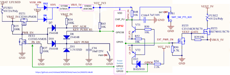
I completed the schema with VUSB_IN, VSYS and OR fonction with D9,D12
SYL
Embedded software and electronics engineer
Hello,
I completed the schema with VUSB_IN, VSYS and OR fonction with D9,D12
SYL
Hello,
On mine, the maxi level indicator of charge is 86% corresponding to 4.18V
I measured USB current with the program "Factory test" and a serial USB device named "UT25".
The value is 131 mA, without interraction.
I also wrote personal comments about all GPIOs (in french, my native language):
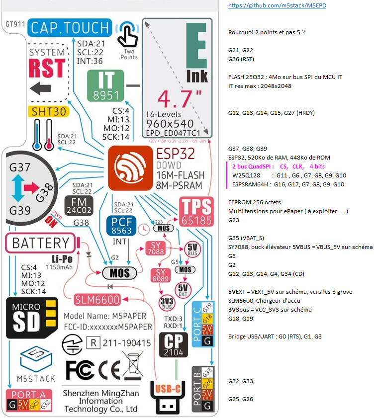
All GPIOs are represented (except non-existent ones : 20, 24, 28, 29, 30, 31)
SYL
@felmue
Indeed GPIO36 is only input.
So I looked for another GPIO used only as input to reverse the 2 GPIO on the pcb.
I found the GPIO27 which tells ESP32 that the IT8951 is ready for a SPI dialogue
IT_SPI_HRDY (schema)
#define M5EPD_BUSY_PIN 27 (M5EPD.h)
EPD.begin(M5EPD_SCK_PIN, M5EPD_MOSI_PIN, M5EPD_MISO_PIN, M5EPD_CS_PIN, M5EPD_BUSY_PIN); (M5EPD.cpp)
m5epd_err_t M5EPD_Driver::begin(int8_t sck, int8_t mosi, int8_t miso, int8_t cs, int8_t busy, int8_t rst)
_pin_busy = busy;
pinMode(_pin_busy, INPUT);
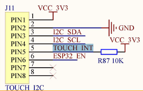
On my pcb, the resistance R87 is absent (unwelded)
All you have to do is reverse the 5 and 16 tabs on the ESP32.
I scraped the varnish and then scanned the pcb.
You have to cut the 2 tracks between the 2 pins of the esp32 and the 2 vias.
then solder 2 thin wires.
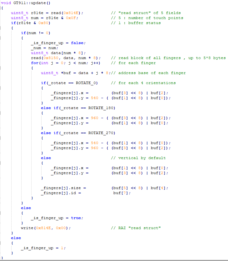
Use :
void GT911::updateB()						// as update but modify by Bricox ...
{
    r814E.reads = read(0x814E);				// "read struct" AND these 5 explicite bits fields
    if(r814E.status)
    {
        if(r814E.touchPts != 0)
        {
            _is_finger_up = false;
            _num = r814E.touchPts;			// "_num" could be definitively replaced by "r814E.touchPts"
            uint8_t data[num * 8];
            read(0x8150, data, _num * 8);	// read block of all fingers , up to 5*8 bytes
            for(int j = 0; j < _num; j++)	// for each finger
            {
                uint8_t *buf = data + j * 8;// address base of each finger
Sorry, comments that were aligned, in my notepad++ by multiple Tabs, are no longer aligned in the snippets viewer
Structure
typedef struct reg814E_s {		//
 union {						// same location of 2 fields of 1 byte
   uint8_t reads;				// this byte
   struct {					// field bits of this byte
     uint8_t touchPts  : 4;	// b0 to b3 : number of touch points
     uint8_t haveKey   : 1;	// b4 : HaveKey
     uint8_t proxi     : 1;	// b5 : Proximity Valid
     uint8_t largeDet  : 1;	// b6 : large detect
     uint8_t status    : 1;	// b7 : buffer status
   };
 };
} __attribute__((packed)) reg814E_t;	// minimize memory alignment
or simpler writing
typedef struct {
  union {              // same location of 2 fields of 1 byte
    uint8_t reads;     // this byte
    struct {           // field bits of this byte, starting with low weight
      uint8_t
        touchPts  : 4, // b0 to b3 : number of touch points
        haveKey   : 1, // b4 : HaveKey
        proxi     : 1, // b5 : Proximity Valid
        largeDet  : 1, // b6 : large detect
        status    : 1; // b7 : buffer status
    };
  };
} reg814E_t;
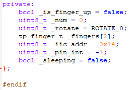
Declarations
private:
    bool _is_finger_up = false;
    uint8_t _num = 0;
    uint8_t _rotate = ROTATE_0;
    tp_finger_t _fingers[2];
    reg814E_t r814E;
    uint8_t _iic_addr = 0x14;
    uint8_t _pin_int = -1;
    bool _sleeping = false;
};
Hello @felmue,
While I was commenting on the source code, I found un bug in the GT911 driver :
_fingers[] can be indexed up to 5
In declaration, _fingers[] can be indexed up to 2
In addition, it would be elegant to use bit fields for describing registers that have specific functions.
An example : 
Hello @felmue
Find 1 output, to put low the INT signal of GT911, have another way possible ....
In the ESP pdf, I found this :
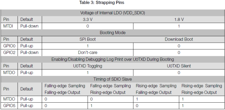
For reuse these pins, an article : https://www.instructables.com/ESP8266-Using-GPIO0-GPIO2-as-inputs/
I think that, in the M5paper, we can use GPIO0 as output.
What you think about ?
hello,
a little bit of electronics (because no present in official doc) :
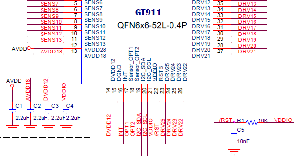
The PFL with C1, C2, C3, C4 R1 and C5:
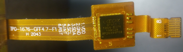
Remark : pin 7&8 are "shield"
Hello guys .... @felmue, @fonix232, @tatar-andrei... and other enthusiasts ....
I have others links for the GT911 driver in cpp
With interrupt : https://github.com/nik-sharky/arduino-goodix/blob/master/Goodix.cpp
No interrupt but handles 5 fingers : https://github.com/caiannello/ER-TFTM0784-1/blob/master/src/touch.cpp
We’ll have to adapt these source codes.
Sorry, i'm not a specialist for interrupts of Arduino framework....I am more familiar with the HAL framework of the STM32.
Thank you for these sustained sharing
@felmue
To fully understand the GT911 controller, download these 2 pdf
https://www.crystalfontz.com/controllers/GOODIX/GT911/464/
https://www.crystalfontz.com/controllers/GOODIX/GT911ProgrammingGuide/478/
Several developments are desirable :
List of 21 other GT911 drivers :
https://github.com/search?q=gt911
including one in cpp:
https://github.com/blackketter/GT911/blob/master/src/GT911.cpp
@fonix232
My apologies, I don’t know how I made that big mistake ... ;>)
You’re right, it’s definitely a native USB.
The red symbol is, for me, that printfoot USB-C connector is on the pcb but not welded.
This part of the schema is not completely greyed out as J10 because the 2 resistors R1 and R60 are welded.
 The Google search with this image did not succeed.
You’d have to look in the symbol library of the design software, I think it’s Altium...
@fonix232
USB-TYPEC/NC is not a real USB port because no bridge.
The connector is USB-C but the line is UART only.
@fonix232
In my professional activity, I use the STM32L476.
Its average power consumption is 15-20mA at 80 MHz.
I use "Stop 2" mode to reduce consumption => 2.3µA (5µs wake-up with many sources).
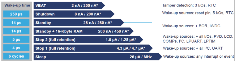
In addition, it has its own RTC with calendar and the ADCs are most linear than ESP32.