[Solved]Schematics for M5StickC?
-
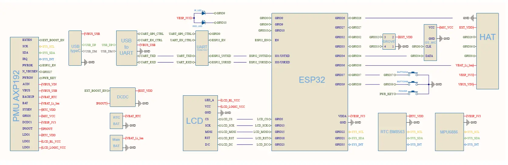
I was looking for the schematic because I wanted to understand whether the IMU interrupt pins were routed to a GPIO.
-
@avg said in [Solved]Schematics for M5StickC?:
I was looking for the schematic because I wanted to understand whether the IMU interrupt pins were routed to a GPIO.
Me too ! ! !
-
M5StickC Schematic
-
@m5stack That is not a schematic. For example: apparently there isn't a single resistor on the M5StickC.
I've got my M5StickC in pieces trying to reduce power consumption for increased battery life, and I can see at least 20 resistors without even counting properly.
When will you be releasing the schematic?
-
@morris45 for the time being. only provide pin map schematic. don't provide electronic component parameters.
-
@m5stack If you won't release the schematic, can you tell us why the M5StickC still draws 2mA in deepsleep, and not 10uA like the ESP32 should?
-
@morris45 i has ask our engineer . even if the esp32 deepsleep, other electronic component still work. like imu, axp192 etc. even if you seting the IMU to sleep mode the esp32 can't possible low power to 10uA.
-
@m5stack If I power down the M5StickC by pressing the power button for 6 seconds, the current consumption is 0mA, so the AXP192 can turn everything off, like IMU, display etc. How do I tell the AXP192 to only turn on the ESP32 and keep the IMU etc turned off?
That way I will only have the current consumption of the AXP192 and ESP32 (10uA).
-
@morris45 we don't have example code to setup it low power to 10ua. even if you shutdown the IMU and screen . current still is mA level
-
@morris45 said in [Solved]Schematics for M5StickC?:
@m5stack If I power down the M5StickC by pressing the power button for 6 seconds, the current consumption is 0mA, so the AXP192 can turn everything off, like IMU, display etc. How do I tell the AXP192 to only turn on the ESP32 and keep the IMU etc turned off?
That way I will only have the current consumption of the AXP192 and ESP32 (10uA).
Seems to me like the IMU MPU6886 is powered via VESP_3V3, which is driven by the AXP192's DC/DC-converter 1 DCDC1, which also supplies the ESP32.
According to the MPU6886 datasheet, the regular power consumption with all 6 axes on is around 2.8mA, which matches your observations of 2mA. You can use the low power modes down to 45µA (only Accelerometer), or Full-Chip Sleep mode at 10µA (see p. 11).
On power up the IMU defaults to Sleep Mode (see p. 32), so maybe it is sufficient to not initialize it. Otherwise you would have to turn it off by writing to register PWR_MGMT. For full power down, no standby must be set (see section 9.9, p. 52.)
Unfortunately the M5StickC-library does not offer an interface for any of those power management features.
@m5stack: It would be a big help to have power management support in the library, and an example that demonstrates different power consumption states (maybe with the coulomb counter to get a real integral power consumption). Also a great example to prove that M5StickC is usable as a wearable and standalone device for more than just a few minutes.
The RTC would be able to trigger an interrupt on a preset alarm time, or with a timer. But I'm not sure if this is sufficiently connected to the PMU AXP192 to wake it up from complete system power down. This would be something @m5stack could probably answer.
-
It is for M5StickC Plus. M5StickC is nearly the same:
https://docs.m5stack.com/assets/img/product_pics/core/minicore/m5stickc_plus/StickC_sch.webp
Hello! It looks like you're interested in this conversation, but you don't have an account yet.
Getting fed up of having to scroll through the same posts each visit? When you register for an account, you'll always come back to exactly where you were before, and choose to be notified of new replies (either via email, or push notification). You'll also be able to save bookmarks and upvote posts to show your appreciation to other community members.
With your input, this post could be even better 💗
Register Login