🤖Have you ever tried Chat.M5Stack.com before asking??😎
  • Sample code for Thermal Unit and Core2?

    3
    0 Votes
    3 Posts
    3k Views
    W
    Thanks for the hint. That code won't compile: 'MLX90640_BadPixelsCorrection' was not declared in this scope. If you comment out the reference to MLX90640_BadPixelsCorrection it compiles and works OK. In the meantime I got a UIFlow version working more or less. Download from https://github.com/wsanders/WSThermalCore2Cam/blob/main/thermtest1.m5f. It's pretty crude but it autoranges OK if the temperature differences aren't too bad. Using ASCII art pixels because it's faster than drawing two rectangle (you STILL can't draw a borderless rectangle in UIFlow!) Sorry - I deleted my previous post accidentally. It was full of errors anyway.
  • Ultrasonic I2C problems

    2
    0 Votes
    2 Posts
    4k Views
    I
    It seems if I set the i2c rate to 100Khz this works.
  • PBHub v1.1 (STM32F030F4p6) FW Source

    stm32 pbhub fw
    1
    0 Votes
    1 Posts
    3k Views
    No one has replied
  • UnitCam quality and compression settings missing for Arduino and Core2

    4
    0 Votes
    4 Posts
    5k Views
    S
    Thanks lot @felmue, I really appreciate. I had guessed the output format can also simply be changed by writing to the ov2640 register. At least it says it on the main page, that the other settings would be available. Anyways, I am fine with working with jpg, but unfortunately I cannot reproduce the jpeg yet in an RGBA8 texture with the given resolution from the provided buffer (~8000 bytes). The photo taken is just white/grey. [image: 1667220436017-8224550e-e22d-41b3-90ed-9e59588730eb-grafik.png] [image: 1667220583609-0cf88125-bb78-4c0a-9827-97a54f63315b-grafik-resized.png] I am just sending the uint8_t buffer over Serial for (uint32_t i = 0; i<frame.size; i++) { Serial.write( frame.buf[i] ); }, and read the bytes to a texture, while filtering for Jpeg Start ff d8 and Stops ff d9 (which I find). [image: 1667221062882-ee39c219-d6c9-44ee-8297-692ab61868f1-grafik.png] The length / size of the buffer ~1000-3000 for the 160x140 resolution, seems suspiciously low though, compared to the relatively good image shown on the Core2 display. Hm.. I assume the buffer has to be uncompressed based on compression settings found in the Jpeg header bytes.. -- Got it working by decompressing jpeg
  • M5StickV Face Detect not working

    1
    0 Votes
    1 Posts
    3k Views
    No one has replied
  • M5CoreInk Serial2 Issue I don't understand

    2
    0 Votes
    2 Posts
    3k Views
    H
    Oh I forgot, and this is how the Serial2 is initiated (MrCore2 and M5CoreInk) : Serial2.begin(115200, SERIAL_8N1, RX_PIN, TX_PIN,true); // Serial2.begin(9600, SERIAL_8N1, RX_PIN, TX_PIN); //Serial port 2 initialization delay(300);
  • M5Core - blank screen

    5
    0 Votes
    5 Posts
    7k Views
    robskiR
    @ajb2k3 tday I've loaded one of old firmwares with old M5burner and it is same...only LCD backlight is on all the time not a single thing being displayed on LCD, if I use ERASE option then backlight is off
  • PoECAM TTL Connection

    5
    0 Votes
    5 Posts
    5k Views
    I
    Hi, I only have one switch available at the moment, but I will see if I can test with another one. Using the FTDI to set the IP without a full reprogramming would be ideal, but I might as well just reprogram it with a static ip. Thank you for the help!
  • M5 Stack ADS1115 address

    3
    0 Votes
    3 Posts
    3k Views
    felmueF
    Hello @nebosa check the ADS1115 datasheet (linked here under Related Link). Section 9.5.1.1 I2C Address Selection describes how to change the I2C address. Looking at the board of my AMeter I can see that it is partly prepared to select a different I2C address. One can move a 10 k resistor from one location to another to switch between 0x48 (default) and 0x49. To select 0x4A or 0x4B requires a bit more work, I am afraid. Below picture illustrates my modification to change the AMeter I2C address to 0x4B. [image: 1665964944391-m5stackameteri2caddr0x4b_20221017.png] Thanks Felix
  • RFID2 Unit and Core2 Processor

    4
    1
    0 Votes
    4 Posts
    6k Views
    F
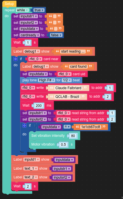
    @falbriard An attempt to write a logic with Blockly & MicroPython code (via UIFlow), able to store up to 1000 characters on a RFID tag: # by Claude Falbriard - QcLab Brazil # RFID tag with RC522 layout from m5stack import * from m5stack_ui import * from uiflow import * import time import unit screen = M5Screen() screen.clean_screen() screen.set_screen_bg_color(0x000000) rfid_0 = unit.get(unit.RFID, unit.PORTA) inputsrt2 = None elecounter = None alldata = None inputstr1 = None inputdata = None inputstr4 = None cardready = None label0 = M5Label('RFID Reader', x=10, y=10, color=0xf5f2f2, font=FONT_MONT_14, parent=None) text_2 = M5Label('text_2', x=10, y=113, color=0xb1ed94, font=FONT_MONT_14, parent=None) text_4 = M5Label('text_4', x=10, y=138, color=0xccf1a6, font=FONT_MONT_14, parent=None) debug1 = M5Label('Debug: ', x=10, y=226, color=0xf09a9a, font=FONT_MONT_14, parent=None) alldata_label = M5Label('alldata', x=10, y=170, color=0xdff2d7, font=FONT_MONT_14, parent=None) inputd1 = M5Label('input data', x=10, y=48, color=0xe8f081, font=FONT_MONT_14, parent=None) text_1 = M5Label('text_1', x=10, y=88, color=0xcbeeb9, font=FONT_MONT_14, parent=None) elecounter = 0 # constructing an RFID RC522 compliant data writer # https://www.blindtextgenerator.com/lorem-ipsum # generate a string with max length of 1000 characters ipsumstr = """Lorem ipsum dolor sit amet, consectetuer adipiscing elit. Aenean commodo ligula eget dolor. Aenean massa. Cum sociis natoque penatibus et magnis dis parturient montes, nascetur ridiculus mus. Donec quam felis, ultricies nec, pellentesque eu, pretium quis, sem. Nulla consequat massa quis enim. Donec pede justo, fringilla vel, aliquet nec, vulputate eget, arcu. In enim justo, rhoncus ut, imperdiet a, venenatis vitae, justo. Nullam dictum felis eu pede mollis pretium. Integer tincidunt. Cras dapibus. Vivamus elementum semper nisi. Aenean vulputate eleifend tellus. Aenean leo ligula, porttitor eu, consequat vitae, eleifend ac, enim. Aliquam lorem ante, dapibus in, viverra quis, feugiat a, tellus. Phasellus viverra nulla ut metus varius laoreet. Quisque rutrum. Aenean imperdiet. Etiam ultricies nisi vel augue. Curabitur ullamcorper ultricies nisi. Nam eget dui. Etiam rhoncus. Maecenas tempus, tellus eget condimentum rhoncus, sem quam semper libero, sit amet adipiscing sem neque sed ipsum. N""" # chop test data string to 256 bytes ipsumstr = ipsumstr[:256] # split a text into 16 bytes elements, max size = 1000 def split_by_n(seq, n): '''A generator to divide a sequence into chunks of n units.''' while seq: yield seq[:n] seq = seq[n:] rc522list = list(split_by_n(ipsumstr, 16)) blkcount = len(rc522list) # process list by RC522 element max 1000 char validptr = [1,2,4,5,6,8,9,10,12,13,14,16,17,18,20,21,22,24,25,26,28,29,30,\ 32,33,34,36,37,38,40,41,42,44,45,46,48,49,50,52,53,54,56,57,58,\ 60,61,62,64,65,66,68,69,70,72,73,74,76,77,78,80,81,82,84,85,86] keyptr = [3,7,11,15,19,23,27,31,35,39,43,47,51,55,59,63,67,71,75,79,83] while True: alldata = '' inputstr1 = '' inputsrt2 = '' inputdata = '' inputstr4 = '' cardready = False wait(1) debug1.set_text('start reading ...') if rfid_0.isCardOn(): debug1.set_text('card found') inputdata = rfid_0.readUid() speaker.playTone(740, 1/2) inputd1.set_text(str(inputdata)) elecounter = 0 for ele in rc522list: blkdata = ele blkaddr = validptr[elecounter] rfid_0.writeBlock(blkaddr,blkdata) elecounter += 1 wait_ms(400) # read data only for debug inputstr1 = rfid_0.readBlockStr(1) inputsrt2 = rfid_0.readBlockStr(2) inputstr4 = rfid_0.readBlockStr(4) # all data stored on tag for blkcount in range (0,elecounter): blkaddr = validptr[blkcount] record = rfid_0.readBlockStr(blkaddr) alldata += record if inputdata == '1e1cb67cc8': power.setVibrationIntensity(80) power.setVibrationEnable(True) wait(0.5) power.setVibrationEnable(False) # show data for debug and validation text_1.set_text(str(inputstr1)) text_2.set_text(str(inputsrt2)) text_4.set_text(str(inputstr4)) alldata_label.set_text(str(alldata)) wait(2)
  • UIflow support for Relay module bases?

    2
    0 Votes
    2 Posts
    3k Views
    felmueF
    Hello @wkearney99 I don't see 4-Relay module in UIFlow (yet). No, I don't think you can use the UIFlow for 4-Relay unit since the I2C registers are different. 4-Relay module uses register 0x10 to control the relay vs. 4-Relay unit uses register 0x11 to control the relay and LED (register 0x10 is a control register). Documentation for 4-Relay module. Documentation for 4-Relay unit. BTW: you could use the default I2C Master blocks (under Hardwares) to control the 4-Relay module. Thanks Felix
  • PaHub2 code for Stamp C3

    8
    0 Votes
    8 Posts
    8k Views
    D
    Thanks terry
  • Stamp C3 I2C relay

    3
    0 Votes
    3 Posts
    4k Views
    D
    Thanks
  • Unit ACSSR U139 mode change, micropython

    6
    0 Votes
    6 Posts
    7k Views
    ajb2k3A
    @teastain That was my hope too and I was disappointed to find it controlled by an esp32 but not wifi accessible :(
  • RFID and UHF-RFID

    5
    0 Votes
    5 Posts
    7k Views
    K
    @gleon m5 core, m5stick and m5paper
  • 4-Relay Unit question

    3
    0 Votes
    3 Posts
    4k Views
    R
    @felmue Thanks for you fast reply Felix! I will.
  • I2C relay change address

    3
    0 Votes
    3 Posts
    3k Views
    D
    Thanks
  • Fuse blew up

    2
    0 Votes
    2 Posts
    3k Views
    ajb2k3A
    Its a 4A SMD fuse. I have a guide here on replacing the fuse is the SSR but it works the same for the Ammeter unit. https://www.hackster.io/AJB2K3/replace-the-fuse-in-the-m5stack-ssr-unit-477a23
  • how to connect to M5stack PoESP32

    2
    0 Votes
    2 Posts
    3k Views
    felmueF
    Hello @xha1e PoESP32 is a unit and meant to be controlled via Groove serial connection using AT commands. May I ask what is the reason you'd like to modify the preinstalled AT firmware? That said, if you look at the schematic you'll see J2 (Download Socket) in the bottom right corner. J2 can be used with an USB serial adapter to modify the preinstalled AT firmware. Note: J2 is internal and not populated. Note: the preinstalled internal firmware can be altered / replaced using Arduino IDE. But please be aware that restoring the preinstalled AT firmware requires the ESP-IDF build environment (which is different from the Arduino IDE). Preinstalled AT firmware source code and build instructions can be found here. Thanks Felix
  • 0 Votes
    5 Posts
    6k Views
    felmueF
    Hello @a1development I am glad to hear you got it working and thank you for reporting back. Thanks Felix