M5StickC: turn off screen completely
-
I poked around the APX192 code, and around a datasheet found here. First, there's this code:
void AXP192::begin(void) {
  Wire1.begin(21, 22);
  Wire1.beginTransmission(0x34);
  Wire1.write(0x10);
  Wire1.write(0xff);  //OLED_VPP Enable
  Wire1.endTransmission();
  Wire1.beginTransmission(0x34);
  Wire1.write(0x28);
  Wire1.write(0xff); //Enable LDO2&LDO3, LED&TFT 3.3V
  Wire1.endTransmission();
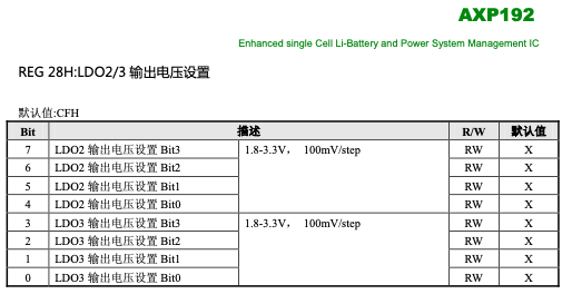
A peek at the datasheet says that REG 28H is power management for LD02 and LD03. Sure thing. That's what the comment in the code above says – along with a hint that LD03 is for the TFT.

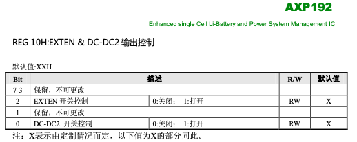
Meanwhile, REG 10H is two ON/OFF switches, for EXTEN and DC-DC2 – commented in the code as VPP_Enable. Bueno.

I am not sure which of EXTEN or DC-DC2 is connected to the OLED (both?), but turning either or both off will cut off the current to the OLED.
Moreover there's this code later:
  Wire1.beginTransmission(0x34);
  Wire1.write(0x12);
  Wire1.write(0x4d); //Enable DC-DC1, OLED_VDD, 5B V_EXT
  Wire1.endTransmission();
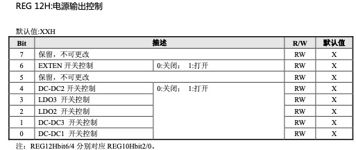
And REG 12H seems to do more of the same as 10H:

Bit 3 turns ON/OFF LD03, which, as we saw above, is supposed to be the OLED. Good odds that setting bit 3 of REG 12H to zero would work too.
I don't have time to test it now, but I'll try later tonight.
-
After a little bit of poking around I managed to turn off the screen:
Wire1.beginTransmission(0x34);
Wire1.write(0x12);
Wire1.write(0b01001011);  // LDO2, aka OLED_VDD, off
Wire1.endTransmission();
This turns off LDO2, and thus the backlight. To turn it back on:
Wire1.beginTransmission(0x34); Wire1.write(0x12); Wire1.write(0x4d); // Enable LDO2, aka OLED_VDD Wire1.endTransmission(); -
@dda Thanks! @ricardocosta can probably check to see how much current is used when backlight is off.
-
While I'm at it, an explanation about
M5.Axp.ScreenBreath(x);. The code is:void AXP192::ScreenBreath(uint8_t brightness) { Wire1.beginTransmission(0x34); Wire1.write(0x28); Wire1.write(((brightness & 0x0f) << 4)); //Enable LDO2&LDO3, LED&TFT 3.3V Wire1.endTransmission(); }What it does is it takes the value you passed, cuts it to 4 bits (0-15) and moves those 4 bits to bits 4-7. Register 28H is voltage control for LDO2 (bits 4-7) and LDO3 (bits 0-3). So the OLED is connected to LDO2.
What that 0-15 value represents is a voltage of 1.8 to 3.3V, in 100mV/steps. So
M5.Axp.ScreenBreath(0);sets voltage to 1.8V, andM5.Axp.ScreenBreath(15);to 3.3V. Not what we really want – as the goal was to set voltage to zero... :-)
Whereas register 12H controls the state (ON/OFF) of a bunch of wires, including LDO2 (bit 2). Hence the code above.

-
Does your code cut the voltage to the backlight only? or to the screen as well?
-
To be tested but I think this turns off OLED_VDD, ie the current to the OLED. Register 10H is said to be for OLED_VPP so setting it to zero could help too.
-
I did a simple test: with only REG 28H the screen stays slightly warm. With both 28H and 10H, the screen cools off after a while. Hardly a scientific test, I know, but seems to point to the need to set both registers.
-
@dda what a wonderful work you have done! I hope this will enable @Multihelix to use M5StickC as a watch (turn off OLED after a timeout and turn on OLED on button press or accelerometer)
-
How are you getting 5 hours of life? it seems you would need <16 ma total drain
Are you sleeping the ESP32?
-
@ws1088 Funny enough I bought my M5StickC with the watch strap and all, but not because I wanted a watch – I don't wear them – but because it enables me to tie it up to my backpack when I do LoRa range tests :-)
-
@dda said in M5StickC: turn off screen completely:
@ws1088 Funny enough I bought my M5StickC with the watch strap and all, but not because I wanted a watch – I don't wear them – but because it enables me to tie it up to my backpack when I do LoRa range tests :-)
why would you use m5stickc to do LoRa range tests? You can get LoRa chip with OLED screen. Do you connect m5stickc to a LoRa chip via I2C? or WiFi AP?
-
I have a lot of different LoRa chips and setups. I have one board, at 230 MHz, that I can connect through the hat connector (I need 3 pins + Vcc/GND). I have transceivers, both at 230 and 433 MHz, I connect to via RS485 (I bought a hat for that, and also some RS485 for my M5Stack cores). etc etc. The smaller the better :-)
-
@maxstack - Yes, I used ESP DeepSleep set to wake on Button A being pressed, but I would say that the 5 hour time was not under ideal conditions, as I occasionally woke up the device to confirm it was still working and to check the time - a resonable activity for a watch.
-
@multihelix Can you post a link to your watch code?
-
@dda said in M5StickC: turn off screen completely:
I did a simple test: with only REG 28H the screen stays slightly warm. With both 28H and 10H, the screen cools off after a while. Hardly a scientific test, I know, but seems to point to the need to set both registers.
I'm looking at this thread to hopefully implement a complete screen turn off, but am not sure what register mask to use (based on quoted post)
Here is what I have, the screen is off but hard to know if the screen has actually been disabled.
void turnOffScreen() {
Wire1.beginTransmission(0x34);
Wire1.write(0x10);
Wire1.write(0b00000000); // 7-3=? | 2=EXTEN | 1=? | 0=DC-DC2
Wire1.endTransmission();Wire1.begin(21, 22);
Wire1.beginTransmission(0x34);
Wire1.write(0x12);
Wire1.write(0b01001011); // 7=? | 6=EXTEN | 5=? | 4=DC-DC2 | 3=LDO3 | 2=LDO2 | 1=DC-DC3 | 0=DC-DC1
Wire1.endTransmission();Wire1.beginTransmission(0x34);
Wire1.write(0x28);
Wire1.write(0b00001111); // 7-4=LDO2 | 3-0=LDO3
Wire1.endTransmission();
} -
@klimbot: I think you have to turn LDO3 and LDO2 off, in your code only LDO2 is off. Take a look at this picture: https://docs.m5stack.com/assets/img/product_pics/core/minicore/m5stickc/m5stickc_05.webp
-
This is how I init my M5StickC in a full black screen way.
M5.begin(0,1,1);
M5.Axp.SetLDO2(false);
M5.Axp.SetLDO3(false);