How to control m5stickc pins via uiflow?
-
G26 could be use only as input. Change pin to another eg. G36 and should work. Alternativelly
Try use Advanced ->PIN blocks
use init block, change mode to OUT and pull to PULL_FLOAT to set your pin in output mode then set your pin with set pin block. -
Hi @robalstona ,
In fact, G36 can only be used as input, I think you should remember it wrong. -
Hi @d3f4u1t ,
I just test it and it work well.
pin G26 still have 3V even I already set it "digital write pin G26 value 0"
Are you measuring the result with a multimeter?
-
@robalstona The error has occured "type object 'Pin' has no attribute 'PULL_FLOAT"
-
Can anyone provide me an example codes?
I want my m5stickc to control this relay via hat pins by UIFlow.

-
@iamliubo Yes, I measuring it with my multimeter
-
try another pullup eg PULL_UP
Probably i mistake with these pins G36 can be use only as input and G26 should work( i wrote this earlier from memory). If you connect this relay module to stick you must connect gnd from module with gnd in stick. If you power relay module from 5V then input signal probably must be a higher than 3.5V (high signal from stick has lower level than needed to trigger relay) on in case when its activate as high signal. Try module alone to connect gnd to in and vcc from module to in, when you will known which signal you must take to trigger LOW or HIGH.
At the last you could use G0, but you could problems when you power up or restart stick (if G0 has been in low when stick run in flash mode) -
ewentually power relay module from lover voltage ~3.5-4V. Then should be trigered with 3.3V in in. But in this case the pover voltage could be too low to correct work of relay( may not work in all cases when you trigger it. I had similar problem when i drive this relay from raspberry pi (also 3.3 logic level)
-
@robalstona Now I figure out that the relay is an active-low device, but it always trigger when i connect it to m5stickc. Is my relay malfunctioned?
-
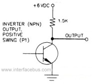
Thats mean the pin where you connect relay is set to low state. So if you want to turn off your relay you must set pin to high mode or use for example transistor inverter (or use not logic gate) to invert your signal if you want activate it in high state signal.
Hello! It looks like you're interested in this conversation, but you don't have an account yet.
Getting fed up of having to scroll through the same posts each visit? When you register for an account, you'll always come back to exactly where you were before, and choose to be notified of new replies (either via email, or push notification). You'll also be able to save bookmarks and upvote posts to show your appreciation to other community members.
With your input, this post could be even better 💗
Register Login