No reset when USB power removed [SOLVED]
-
That has been the situation with the m5stack cores since the beginning, unfortunately. There have been some users on twitter that added a capacitor as a solution, but there is no official fix from m5stack on this issue.
See this discussion: http://community.m5stack.com/topic/1161/m5stack-gray-reboots-when-usbc-power-removed
-
There is a way to attach a diode to the Battery Module.
Blog:USB Cable and Reset prevention
https://macsbug.wordpress.com/2020/04/07/usb-cable-and-reset-prevention/ -
@world101 Thanks for the reply. I have ordered some 2200uF caps to try. I did try 400uF but that isn't enough to keep the M5 from resetting. The caps might also need a resistor to limit inrush current when powering on as the M5 didn't always start up when power was applied. I'll update next week when I get the caps.
-
@macsbug The diode works perfectly to keep the M5 from resetting but it does change some of the behaviour with powering on/off.
-
@gregfordyce said in No reset when USB power removed?:
@macsbug The diode works perfectly to keep the M5 from resetting but it does change some of the behaviour with powering on/off.
I was going to try that as well. What power on/off behaviors have changed when you tested the diode solution?
-
@world101 What I am trying to do is to have the M5 turn on when it gets power, stay on when power is removed without resetting so I can do some house keeping and then turn it off. The next time it gets power it should turn back on. With the diode connected the M5 thinks it still has power from the USB so it won't turn off from the power button. I am also concerned with draining the battery excessively.
However I am thinking if the diode is replaced with a mosfet/transistor then it could be controlled from one of the GPIO pins. Experimenting with plugging in the diode (I'm using a 1N5818 ), the M5 will turn on and off when the diode is plugged in and unplugged. I am still struggling with getting the M5 to turn on reliably when is gets power either from the USB or the diode but I do have it reliably turning off when removing the diode after removing the USB power.
-
I seem to have 2 profiles! oops.
It looks like a MAX40200 will be the answer. It acts as an ideal diode that can also be switched off. I'll order some for testing and report back.
-
The MAX40200 is a great idea.
- I want a power switch for M5Stack 700mA BATTERY MODULE.
- I have switched on the Battery side.
Example 1: AA, AAA battery adapter for M5Stack.
https://macsbug.wordpress.com/2019/04/30/aa-aaa-battery-adapter-for-m5stack/
Example 2: M5STACK Strongest 2400 mAh Battery Module
https://macsbug.wordpress.com/2018/08/20/m5stack-strongest-2400-mah-battery-module/
Example 3: Low price Battery Module of M5STACK
https://macsbug.wordpress.com/2018/06/23/low-price-battery-module-of-m5stack/
-
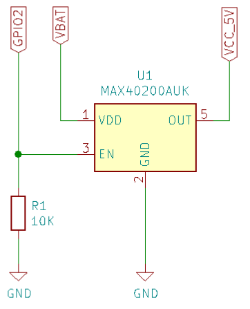
@macsbug Thanks for the links to your projects. For my use the 110mWh battery is all I need. I've done some testing with the diode connected between VBAT and 5V. As the built-in cell doesn't have any protection other than the IP5306 there is a risk that the battery could be over-discharged. I watched the cell voltage drop to 2.4 volts with the diode connected! Normally the IP5306 shuts down the M5 if cell voltage drops to 3.0 volts but the diode prevents this. So with this in mind here's a schematic of how I intend to connect the MAX40200.

R1 is a pulldown to ensure the battery isn't discharged when the M5 is off, and if the cell voltage drops to 3.0 volts and the IP5306 shutsdown the M5, the pulldown should ensure that the MAX40200 shuts off. Also by using GPIO2, the MAX40200 can be controlled from software in the M5 which means that I can use the software to allow the M5 to continue to run uninterrupted if the USB power is removed and then shut it down later as required. -
I'll try and stick with this profile for all future posts. :-)
Using the schematic above and this sketch, MAX40200.ino, I am now able to remove the USB cable without resetting the MAX40200.
The sketch is the digital clock example with 7 lines of code added. The code sets the M5Stack to power off instead of resetting when the USB power is removed, then enables the MAX40200 by setting GPIO2 as an output (HIGH). Then if button A is pressed GPIO2 goes LOW. When GPIO2 is high the MAX40200 acts as a diode and will feed BAT to the 5V pin. This prevents a reset when unplugging the USB cable. Pressing button A drives GPIO2 LOW which switches off the MAX40200. This should prevent excessive battery drain because once battery voltage drops to 3.0 volts the ESP32 is shutdown and that shutdown will also drive GPIO2 LOW.
The only thing left to do is to configure the M5Stack to turn on when power is connected. Sometimes it does and sometimes it doesn't, I think it has to do with how long it's been off, further investigation is required.
-
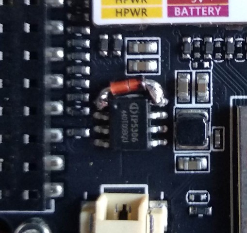
By adding a 1N4148 diode across pins 1 & 8 of the IP5306 the M5Stack is forced to turn on whenever the power is connected to the USB port. Note that if you do this mod it will mean that you won't be able to switch off the M5 whenever power is connected but for my application this doesn't matter. I need the M5 to be on whenever power is connected.

I've used a PROTO module to house the MAX40200 and connected as per the schematic above. My program sets GPIO2 HIGH in the setup loop and after detecting that power has been removed, and completing required house keeping routines, it will set GPIO2 LOW which switches off the MAX40200 and removes VBAT from VCC_5V.
-
Can confirm the m5stack core2 aws iot edukit edition suffers this same behavior.
I don't trust myself to do the tiny soldering, this is incredibly disappointing.