GROVE2GROVE and 5V DC fan
-
Hi,
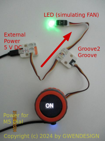
Following this post , how do I connect a 5V DC to the Grove2Grove unit?
A simple scheme will be very helpful (as I am a newbie)
Can it get the power directly from the Grove? Or I need external power supply?Thanks
-
@l-roca Are you referring to Unit 148?
What are you going to control/measure?
What is the controller, i/e. Core? Atom, etc.?
What program do you use for downloading? -
@teastain Hi, unit 148, M5Stack Dial and UIflow 2
-
@l-roca Oh, sorry I only know Arduino IDE.
Having said that, I can't get it working right now for some reason.
There is a UIFlow version here:
https://docs.m5stack.com/en/unit/unit_grove2grove
at the very bottom of the page. -
@teastain Arduino code will also be fine ;-). How do I connect the fan to the unit?
-
@l-roca There are two direct way to provide additional power to grove devices and that is to use this: https://shop.m5stack.com/products/connector-grove-to-usb-c
or this:
https://shop.m5stack.com/products/5v-buck-converter-unitme3116am6g
Via this:
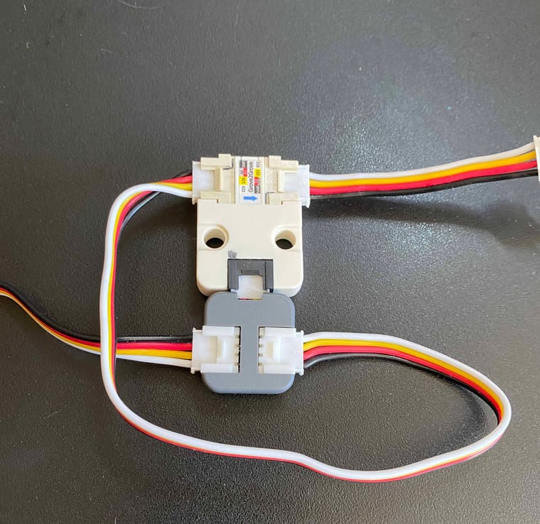
https://shop.m5stack.com/products/grove-t-connector-5pcs-a-packYou disconnect the 5v wire going to the controllers and connect 5v and the supplies GND to the marked pins.
You MUST make sure there is NO direct 5V connection between the power supply and controller.
You need to learn about electronics before connecting anything none M5Stack to M5Stack components.
-
Hi guys
@ajb2k3 : Groove2Groove 5 V line is not connected between the white and black Groove connector by default as R1 isn't populated (at least not in my unit). See schematic here.
@l-roca : the wiring goes as follows:
ext. 5 V        Groove2Groove        FAN
 5 V (red)  ---> 5 V     5 V --->  (red) 5 V
GND (black) ---> GND     GND ---> (black) GND

                 GND   5 V  D.IN
               (black)(red)(yellow)
                  ^     ^     ^
                  |     |     |
                  |     |     |
                M5Dial  (Port B)
You can find the UIFlow2 example in the Project Zone: M5Dial_Grove2Grove_Test_UIFlow2.1.3
Thanks
Felix -
@felmue Thanks! Works perfectly. I too found R0 not connected/installed. My mistake was low side switching, whereby I had the LED upstream.
Your technique and explanation was perfect!
My complaint with M5Stack is they did not show the external hookup. pwr supply, load at all. You diagram made it work. -
@l-roca With Felix's help I got the power on/off working on an AtomS3, which is a 'kissing cousin' to the Dial. I have not yet got the Imeasure working, maybe today!?
If you are interested in my Arduino IDE sketch, contact me by email:
teastain@me.com -
-
@l-roca It's your choice. If the load is within the 5V current output of the Dial, (which is 1000mA) then all you need is a M5Stack splitter (T-connector).
https://shop.m5stack.com/products/grove-t-connector-5pcs-a-pack
I just confirmed that now.

-
@teastain I wasn't aware of the non connection as I dont have the unit, thanks for pointing this out so this revision is based on my designs and feedback.
I need to get some for the Stick projects I have here.