COM.LoRaWAN868 v2.0 Power requirements
-
From what I understand, the COM.LoRaWAN868 v2.0 module has 5V power requirements due to the LoRAWAN chip. To make this work, one thus has to power, via the provided 5.5mm barrel connector. This connector, depending on DIP switch settings can handle input of either 12VDC or 5VDC . In the case of 12VDC, the JW5033H voltage regulator IC steps down the voltage to the needed 5VDC.
Now I am wondering a couple of things:
-
Is 5V power absolutely necessary to get this module working? Is this needed due to the requirements of the particular LORA chipset?
-
If I power the module with the 5V, via the barrel connector, does this power the M5Stack device as well? (in my case I am using a Fire)
-
If 5V is required, then could I not just get a 3v To 5v Boost Converter and wire it into the power provided by the battery in the Fire?
Thanks!
-
-
Hello @whotopia
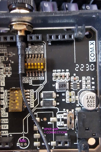
if you look at the schematic you'll see that the DC input voltage always goes to the step down converter (independent of the S1 input switch position). The input voltage is not 5 V or 12 V - it can be anything from 5 V to 12 V.
(Please note: 5 V is actually a bit low as with 5 V the step down converter only is able to produce about 4.5 V.)
The input voltage switch determines which voltage goes to the green LoRaWAN board. If set to 5 V then the output voltage of the step down converter goes to Vin of the green board. If set to 12 V then whatever voltage is applied externally goes to Vin of the green board.
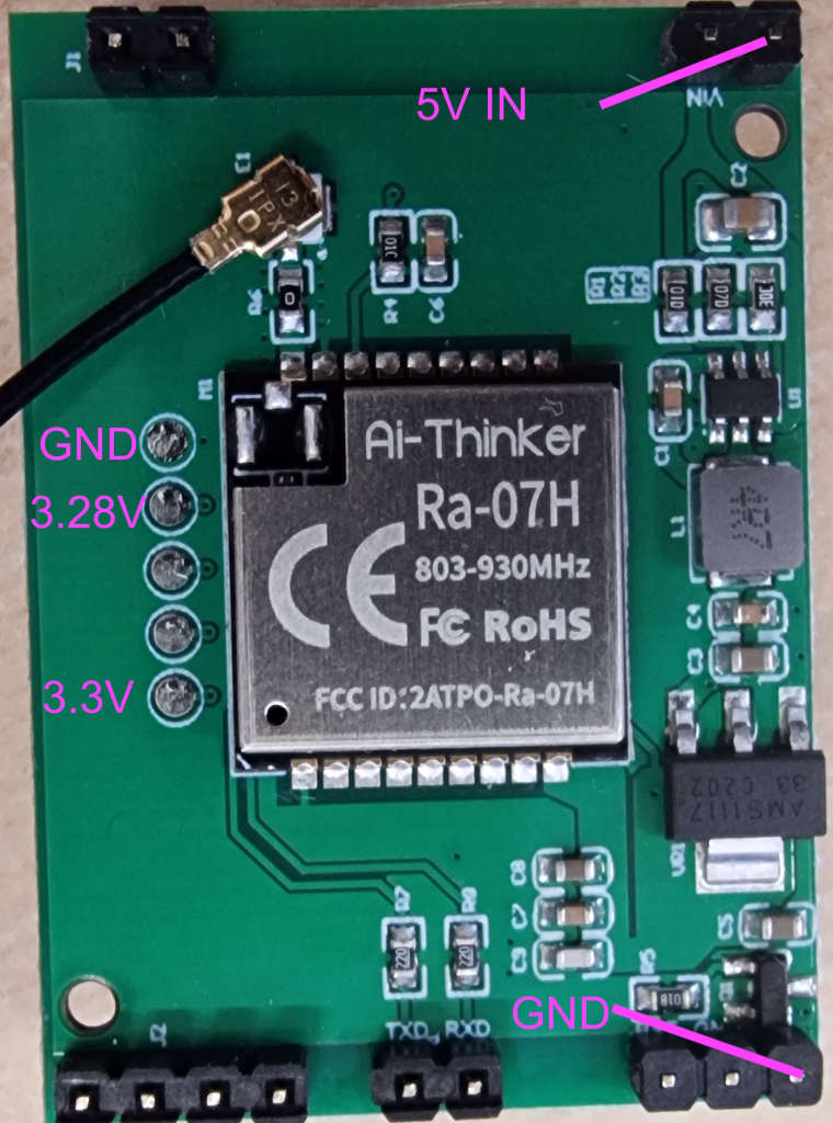
The green board has a separate voltage regulator which seems to generate 3.3 V for the LoRaWAN chip. (Whether that is the only voltage required I cannot tell as there is no schematic for the green board.)
What you can try is the following: Set the power input switch to 5 V and run the Fire from battery. This should generate 5 V on the MBus which then goes to Vin of the green board.
Please note: While I have other COM.X modules I was able to measure the output voltage of the step down converter when only fed with 5 V. However I do not have the COM.LoRaWAN868 v2.0 to test with.
Thanks
Felix -
Hello @felmue
Thanks for your note. You're completely correct.
I've set the DIP switch to 5V. When in that configuration
With the COM.LoRaWAN868 v2.0 connected to the Fire board and it's battery (in my case M5GO battery + a BATTERY 13.2 for long life), I get 5V going into the green board from the main PCB. See:
And as you say there is a regulator which drops the voltage to 3.3V (in my case ~4.9V in, then I see 3.28V and 3.3V at the test pads but that could be due to my cheap meter).
So then, I guess the COM.LoRaWAN868 v2.0 should actually work without any additional power source? I'm going to test that next. It should as I think, as aside from the voltage regulator, the green board doesn't seem to have anything active components on it.
The main board is a bit confusing as it also seems to have unused elements wherein one could also have a microphone MIC and a SPKR connected to it, but these elements remain unpopulated. I wonder what that was for.

Thanks!
-