Connecting M5stack to PCB with header and GPIO capacity.
-
Hi M5stack community!
I'm considering using M5stack Core2 or Cores3 in a project. I want to integrate it to control some SPI and GPIO on my PCB. I'm concerned that it does not have enough GPIO capasity for my project as i understood that most GPIO's are used by existing sensors or components.
-
If i want to use the LCD with touch and maybe the speaker, how many GPIO's (only digital write) do i have left? I need at least 10+
-
What kind of header should i use to make it connect flush with my PCB?
Thanks!
https://docs.m5stack.com/en/core/core2
https://docs.m5stack.com/en/core/CoreS3 -
-
I spent a few hours last month trying to identify what free GPIO existed.
This is what I ended up with, but keep in mind it is not m5stack official, just what I could piece together.
it looks like you -might- potentially have 10 available on the S3, including the 4 used by actual B and C ports.
GPIO #s:
5,6,7,8,9,10,17,18,26,27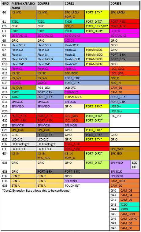
-
Also, see the readme text at https://github.com/m5stack/M5Unified
-
@mtylerjr Thank you for this info and link.
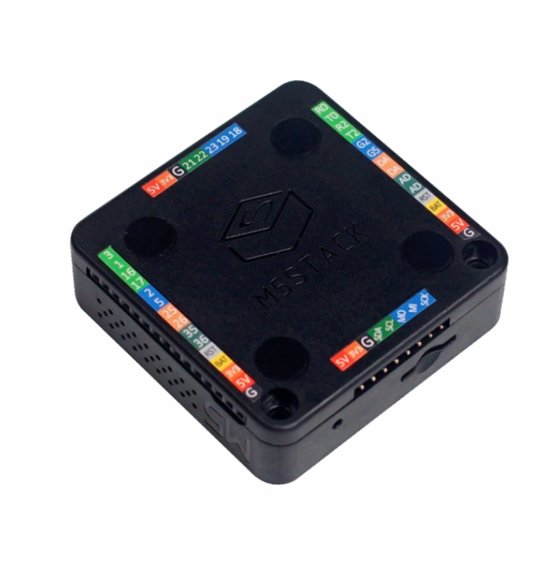
Sidenote: The unique thing about the Core Basic is that it comes with a lot of I/O broken out at the sides of the base/battery box.

Two sides are female connectors and the other two sides are the directly corresponding male pins.
This was in a time gone by where beginner projects had a lot of single pin discrete sensors.
Later, the built-in I2C became more popular and of now my big HVAC desktop controller has zero discretes, one I2C temp sensor and the rest of the I/O is the built-in ESP_NOW, which is amazing.
-Terry -
-
@mtylerjr As i'm intending to use SPI, do you think i could use G35-G37? Maybe even G38-G39 as i dont need the camera.
-
Hmm GPIOs 26/27 may not exist on the CoreS3 after all
-
@mtylerjr The Core Basic has 15 GPIO peripherally arranged in the battery base, as well as generous grounds and voltage options.
-
@teastain Wow, ok! I assume they are available without the battery case on the header too? (I intend to use it as a 'hat' that i just pop into my system). Thanks!
-
@haavardmk In My Opinion the brilliant M5Stack Core series were meant for stand-alone use and could be mounted on a DIN rail, and many other types.
But...they DO sell this set of 10 M-BUS connectors!
https://shop.m5stack.com/collections/m5-accessories/products/2-15-pin-header-socket-for-13-2-module-10pcs
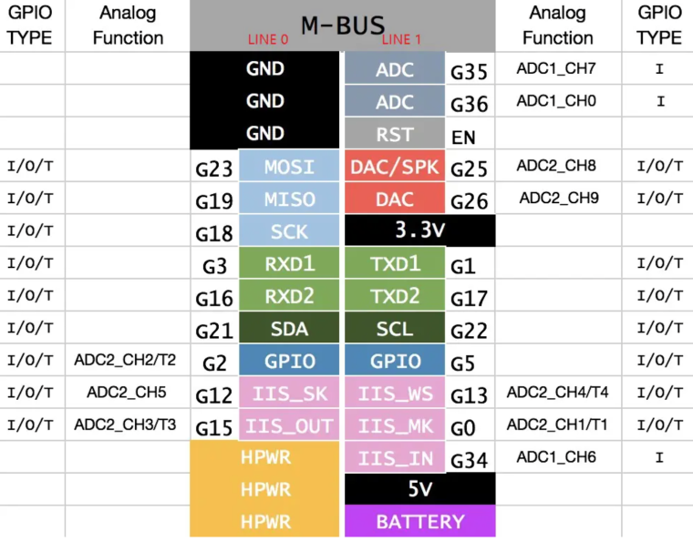
As you know the M-BUS breaks out I2C, SPI and GPIO, two power voltages and grounds !
Core Basic:
Again IMHO I feel the lack of pins that many many Arduino, ESP32, M5Stack hobbyists anguish over can be overcome with I2C and ESP_NOW!
-Terry -
@haavardmk I dont know the answer to your question., I am experimenting to see which GPIO I can use.
I made a small program on my coresS3, to use gpios 10 and 5 with the rotate/angle unit, and it "works" but hangs oddly for a logn time every several measurements. No idea if that is because GPIO10 is meant to be a "BUS ADC" with some special quality, or some other odd software thing. But it is likely something abuot my device, as I am using wires soldered inside to the 5v pin, GND and the two bus gpio pins on the inside of my DIN base, and gpio10 has its own weird little offset pin on the DIN base pcb
Hello! It looks like you're interested in this conversation, but you don't have an account yet.
Getting fed up of having to scroll through the same posts each visit? When you register for an account, you'll always come back to exactly where you were before, and choose to be notified of new replies (either via email, or push notification). You'll also be able to save bookmarks and upvote posts to show your appreciation to other community members.
With your input, this post could be even better 💗
Register Login