Default the GPS and GSM modules are partially disconnected from the M5Stack bus.
You must bridge the contact areas for connection.
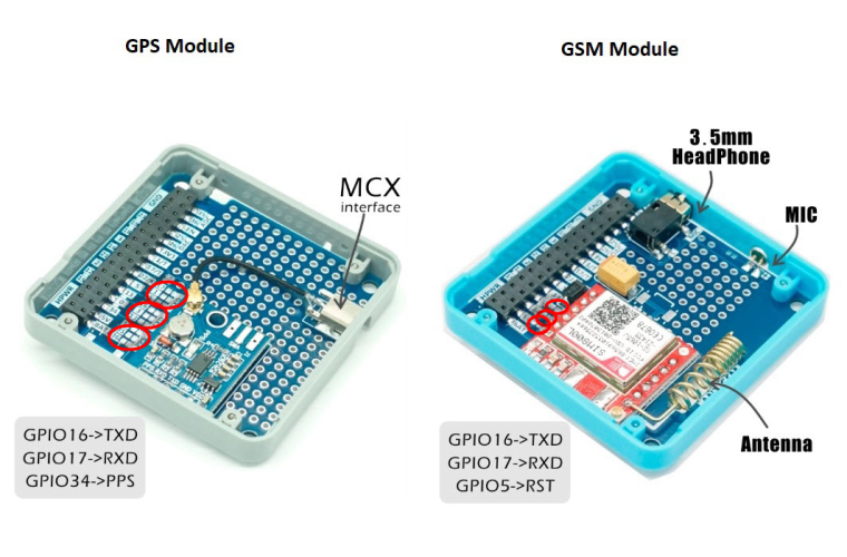
The GSM module has not alternatives for connection. It uses GPIO16 and 17 for UART and GPIO5 for reset.
The GPS module has alternative connections. 16&17 or 1&3 or 5&13 for UART. If you d'not need a PPS-signal, you can not bridge it at all.
BUT.
GPIO 1&3 is used USB-UART (CP2104).
I d'not know how to use GPIO 5&13 like a UART. This is not a typical application for ESP32.
Posts made by X-Dron
-
RE: GPS + GSMposted in FAQS
-
RE: External power to header ?posted in PRODUCTS
@drwino
I'm sorry for missprint. Of course pin "5V". :)
I said the best and most problemless way is to use the usb connector of M5Stack. You could make a special USB cable only with 5V.
All other methods have nuances.
See M5-Core-Schematic.
The simplified power scheme looks like this.
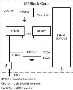
VCC_5V, VCC_3V3, Vbat are connected to the bus, V_USB is not.
if you connect external power to VCC_5V then- A special USB programming cable with the USB 5V disconnected 'll not work. Course CP2104 is not powered.
- If you want to program simply turn off the external power supply 5V. For example to use a jumper.
- You can try to use a diode. But I do not have confidence.
- The battery is not charged.
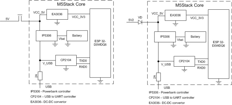
I want to connect external 5V power to the V_USB wire and remove the USB-fuse.
In this case all will powered and 5V from the USB is disconnected. Battery works too.
All must have a common GND.
-
RE: External power to header ?posted in PRODUCTS
- The easiest is to use the USB cable and connect the 5V to it.
2.If you do not need a battery, you can connect to pin 5 on the bus.
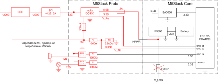
3.I'm going to use such a power scheme. Red lines are new wires.
HPWR is not used in M5Stack now. it is presented only on the bus.
- The easiest is to use the USB cable and connect the 5V to it.
-
RE: Sim800lposted in PRODUCTS
@jpilarski 在 Sim800l 中说:
Is the mic on GPIO5
No. mic and headphone are connected direct to SIM800L module.
GPIO5 is reset.

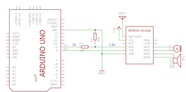
Interconnection
M5 Stask <> SIM800L
Vbat - Vcc (3.7-4.3V)
GPIO16(RX) - TXD
GPIO17(TX) - RXD (must be not direct 3.3V > 2.5V)
GPIO5 - RST
GND - GNDRING is not used.
DTR is not used.MIC+, MIC- to microphone.
SPK+, SPK- to headphone.Example for Arduino
-
RE: Sim800lposted in PRODUCTS
If you can Russian the best manual for SIM800L here
http://codius.ru/articles/GSM_модуль_SIM800L_часть_1
Many sketches for Arduino that can be easily conversion to M5 Stask.
Just replace
#include <SoftwareSerial.h>
SoftwareSerial SIM800 (8, 9); // 8 - RX Arduino (TX SIM800L), 9 - TX Arduino (RX SIM800L)
toHardwareSerial SIM800 (2); // pin 16 = RX, pin 17 = TX
for example
https://yadi.sk/d/SxWs6t0x3UBco6 -
RE: Review "LORA"posted in Lessons and Guides
Is this module compatible with Sim800L?
Both use GPIO-5. -
RE: How to save data without SD card?posted in PRODUCTS
use "Preferences" class
#include <Preferences.h>Preferences preferences;
void setup() {
Serial.begin(115200);
Serial.println();// Open Preferences with my-app namespace. Each application module, library, etc
// has to use a namespace name to prevent key name collisions. We will open storage in
// RW-mode (second parameter has to be false).
// Note: Namespace name is limited to 15 chars.
preferences.begin("my-app", false);// Remove all preferences under the opened namespace
//preferences.clear();// Or remove the counter key only
//preferences.remove("counter");// Get the counter value, if the key does not exist, return a default value of 0
// Note: Key name is limited to 15 chars.
unsigned int counter = preferences.getUInt("counter", 0);// Increase counter by 1
counter++;// Print the counter to Serial Monitor
Serial.printf("Current counter value: %u\n", counter);// Store the counter to the Preferences
preferences.putUInt("counter", counter);// Close the Preferences
preferences.end();// Wait 10 seconds
Serial.println("Restarting in 10 seconds...");
delay(10000);// Restart ESP
ESP.restart();
}void loop() {}