Using Grove - RGB LED Stick with ATOM Matrix?
-
Hello, any tips on how to use this grove LED stick? I tried the example on wiki with pins 26 and 32 (from docs on ATOM), various brightness levels, but nothing really works. It always crashes. Only modifications I did to the example were changing the pin, brightness and adding
M5.begin(true, true, true);.Guru Meditation Error: Core 1 panic'ed (Interrupt wdt timeout on CPU1) Core 1 register dump: PC : 0x40081117 PS : 0x00050034 A0 : 0x400841ec A1 : 0x3ffbeba0 A2 : 0x00000002 A3 : 0x3ff56000 A4 : 0x01000000 A5 : 0x00000001 A6 : 0x0000001a A7 : 0x3ffbff48 A8 : 0x00000001 A9 : 0x3ffbd6a0 A10 : 0x00000000 A11 : 0x00000000 A12 : 0x00060023 A13 : 0x3ffbc22c A14 : 0x00000000 A15 : 0x00000000 SAR : 0x00000018 EXCCAUSE: 0x00000006 EXCVADDR: 0x00000000 LBEG : 0x00000000 LEND : 0x00000000 LCOUNT : 0x00000000 Core 1 was running in ISR context: EPC1 : 0x400e35ca EPC2 : 0x00000000 EPC3 : 0x400ecfca EPC4 : 0x40081117 ELF file SHA256: 0000000000000000 Backtrace: 0x40081117:0x3ffbeba0 0x400841e9:0x3ffbebc0 0x400ecfc7:0x3ffbc6b0 0x400e35c7:0x3ffbc6d0 0x400889ea:0x3ffbc6f0 0x400874f5:0x3ffbc710I tried some I2C scanner (don't really know, how it works) and only device it lists is 0x68. Since it does show it even after disconnecting the LED strip, I guess it's something integrated and not the LED strip? I am quite new to this, so it's probably something silly...
-
Hello @mnf
have you tried the stock example driving the 25 built-in LEDs? If that works, find where the GPIO is defined for the built-in LEDs (e.g. GPIO27) and change that to the GPIO used for the external LEDs (e.g. GPIO32). (Don't forget to change the number of LEDs from 25 to 10.)
BTW: These LEDs are controlled with one single line (clock and data combined) whereas I2C uses two lines (one for clock and one for data). That is the reason the I2C scanner didn't find anything in addition to 0x68 (built in IMU) with the LED Stick attached.
Thanks
Felix -
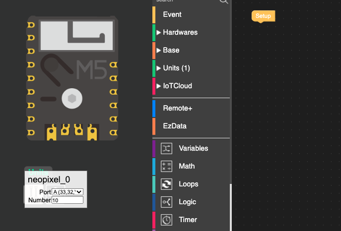
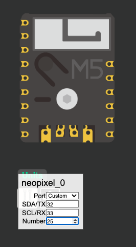
You should be able to use it as a RGB Unit but you may need to define a custom port just to flip which IOpins to use.

by default the pins are set as 33/32 and so if you select custom port you can try setting them to 32/33 (flipping the defined IO pins around.

Opps that should be 32 and 26 changing to 26 and 32, Sorry!
-
Got it to work 😄. The issue was the
M5.begincall. I was passingtruetoDisplayEnable, but I guess there is some collision, so the device can't drive the strip and the matrix display at a same time. For my project the strip alone is good enough, so disabling the display is not a problem.#include <Arduino.h> #include "M5Atom.h" #include "Adafruit_NeoPixel.h" #define PIN 32 #define NUMPIXELS 10 #define DELAYVAL 500 Adafruit_NeoPixel pixels(NUMPIXELS, PIN, NEO_GRB + NEO_KHZ800); void setup() { M5.begin(true, true, false); pixels.setBrightness(255); pixels.begin(); Serial.println("\nGroveLedStickTest\n"); } void loop() { pixels.clear(); for (int i = 0; i < NUMPIXELS; i++) { pixels.setPixelColor(i, pixels.Color(255, 0, 255)); pixels.show(); delay(DELAYVAL); } }