PIN number and shields
-
Thank you PlayTheGame, it's not clear for me...
can you help me on a concrete example?
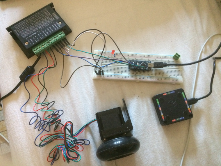
I have a step motor driver TB6600, I use the following arduino sketch by connecting the PIN 2, 5 and 8 on the Arduino Nano.// defines pins numbers
const int stepPin = 5;
const int dirPin = 2;
const int enPin = 8;void setup() {
// Sets the two pins as Outputs
pinMode(stepPin,OUTPUT);
pinMode(dirPin,OUTPUT);
pinMode(enPin,OUTPUT);
digitalWrite(enPin,LOW);}
void loop() {
digitalWrite(dirPin,HIGH); // Enables the motor to move in a particular direction
// Makes 200 pulses for making one full cycle rotationfor(int x = 0; x < 200; x++) {
digitalWrite(stepPin,HIGH);
delayMicroseconds(200);
digitalWrite(stepPin,LOW);
delayMicroseconds(200);
}delay(1000); // One second delay
digitalWrite(dirPin,LOW); //Changes the rotations direction
// Makes 400 pulses for making two full cycle rotationfor(int x = 0; x < 400; x++) {
digitalWrite(stepPin,HIGH);
delayMicroseconds(500);
digitalWrite(stepPin,LOW);
delayMicroseconds(500);
}delay(1000);
}
I would like to use the same thing on the m5stack but I can not find the good PIN.
thank you
-
@fameuhly 在 PIN number and shields 中说:
I would like to use the same thing on the m5stack but I can not find the good PIN.
thank you
-
Yes, i've seen. I've bought one of this but the connector on the nema 17 is not the good one to plug on the stepmotor module.
-
@fameuhly 在 PIN number and shields 中说:
Yes, i've seen. I've bought one of this but the connector on the nema 17 is not the good one to plug on the stepmotor module.
Do what I did.
I brought some of these and cut the old connector off the nema and soldered these https://www.ebay.co.uk/itm/Seeed-Studio-Grove-Universal-4-Pin-20cm-Unbuckled-Cable-5-PCs-Pack-SS05008/282979497546?hash=item41e2e4764a:g:9MgAAOSwU~Fbq2A3 on the end. -
I have a step motor driver TB6600, I use the following arduino sketch by connecting the PIN 2, 5 and 8 on the Arduino Nano.
// defines pins numbers
const int stepPin = 5;
const int dirPin = 2;
const int enPin = 8;void setup() {
// Sets the two pins as Outputs
pinMode(stepPin,OUTPUT);
pinMode(dirPin,OUTPUT);
pinMode(enPin,OUTPUT);I would like to use the same thing on the m5stack but I can not find the good PIN.
Include right libraries and use a stepmotor library with non blocking code (interrupt driven, so you can update the display, play sound etc.). Anyway for a quick test you can modify your code. Here I use pin 13, but there are many free pins.
#include <M5Stack.h>
const int stepPin = 5;
const int dirPin = 2;
const int enPin = 13;//add this to setup
void setup() {
m5.begin();
pinMode(stepPin,OUTPUT);
pinMode(dirPin,OUTPUT);
pinMode(enPin,OUTPUT);M5.Lcd.clear(BLACK);
M5.Lcd.setTextColor(RED);
M5.Lcd.setTextSize(2);
M5.Lcd.setCursor(65, 10);
M5.Lcd.println("STEPMOTOR");
M5.Speaker.mute();//add this to loop
void loop() {
m5.update();Connect ground, Pin 2, 5, 13 with your driver. However, because the M5stack is 3.3V the signal level might be too low for your driver expecting 5V and you need a level converter.
-
Thank you for the info @ajb2k3 and @PlayTheGame !
I will order the connectors.
I did the quick test and it works well, but I used the proto module to get the pins numbers.Is there a table with the corresponding pin numbers of the proto module and the back of the m5stack core?
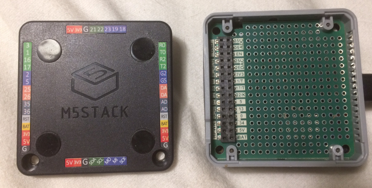
For example, where is pin 13 on the back of the m5stack core?I have everything to learn!
-
Well, the confusions epicenter is at M5stack team, it is not your fault @fameuhly
The programming pin list in Arduino is
static const uint8_t TX = 1;
static const uint8_t RX = 3;
static const uint8_t TXD2 = 17;
static const uint8_t RXD2 = 16;
static const uint8_t SDA = 21;
static const uint8_t SCL = 22;
static const uint8_t SS    = 5;
static const uint8_t MOSI  = 23;
static const uint8_t MISO  = 19;
static const uint8_t SCK   = 18;
static const uint8_t G23 = 23;
static const uint8_t G19 = 19;
static const uint8_t G18 = 18;
static const uint8_t G3 = 3;
static const uint8_t G16 = 16;
static const uint8_t G21 = 21;
static const uint8_t G2 = 2;
static const uint8_t G12 = 12;
static const uint8_t G15 = 15;
static const uint8_t G35 = 35;
static const uint8_t G36 = 36;
static const uint8_t G25 = 25;
static const uint8_t G26 = 26;
static const uint8_t G1 = 1;
static const uint8_t G17 = 17;
static const uint8_t G22 = 22;
static const uint8_t G5 = 5;
static const uint8_t G13 = 13;
static const uint8_t G0 = 0;
static const uint8_t G34 = 34;
static const uint8_t DAC1 = 25;
static const uint8_t DAC2 = 26;
static const uint8_t ADC1 = 35;
static const uint8_t ADC2 = 36;
However, M5Stack team decided to name the pins in the limited info differently in different places. 13 on the pin header and the proto module is G13 but it is not routed to the core module edge pins. I am really wondering why they did two SPI connectors on opposite sides, but forgot the mandatory chip select pin? At least G2 and G5 have the same colour.
You can try with G16 and G17 on a Core (not on Fire - PSRAM!) because most likely you wont need the second UART.
-
@playthegame 在 PIN number and shields 中说:
Thank you, I will continue my tests. The matches will help me!
-
Hello, happy new year !
I'm back on my tests...I have a lot of problems.
1 : problem for uploading sketch on the board, i should remove the "bottom" of the m5stack and bush the boot button for it to work ! And sometimes it fails anyway...2 : I tried to stop the pins on the "bottom" with the sketch "blink" and those that work are :
0, 2, 3, 5, 12, 13, 15, 16, 17, 19, 21, 22, 26
The others (1, 18, 23, 25, 34, 35, 36) doesn't work.3 :
I don't understand why the same simple sketch work fine on arduino uno board and don't work on the m5stack.
I put the #include <M5Stack.h>, m5.begin(), m5.update... But i have the impression that the selected pins don't work.What i'm doing wrong ?
-
@farmeuhly said in PIN number and shields:
Hello, happy new year !
I'm back on my tests...I have a lot of problems.
1 : problem for uploading sketch on the board, i should remove the "bottom" of the m5stack and bush the boot button for it to work ! And sometimes it fails anyway...2 : I tried to stop the pins on the "bottom" with the sketch "blink" and those that work are :
0, 2, 3, 5, 12, 13, 15, 16, 17, 19, 21, 22, 26
The others (1, 18, 23, 25, 34, 35, 36) doesn't work.3 :
I don't understand why the same simple sketch work fine on arduino uno board and don't work on the m5stack.
I put the #include <M5Stack.h>, m5.begin(), m5.update... But i have the impression that the selected pins don't work.What i'm doing wrong ?
Because the esp32 and the mega328p do not have the same pins.
The AtMegas have defined pins but the esp32 uses a matrix of functions that can be assigned to each i/o pin.Check out the esp32 data sheet for these functions.
Hello! It looks like you're interested in this conversation, but you don't have an account yet.
Getting fed up of having to scroll through the same posts each visit? When you register for an account, you'll always come back to exactly where you were before, and choose to be notified of new replies (either via email, or push notification). You'll also be able to save bookmarks and upvote posts to show your appreciation to other community members.
With your input, this post could be even better 💗
Register Login