Object Tracking on myCobot 280 Jetson Nano: A Case Study
-
Introduction
When we saw a video on YouTube of someone using a robotic arm to achieve object tracking, it deeply inspired us. We became very interested in this project and decided to independently develop a similar program.
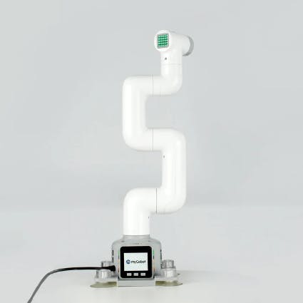
myCobot 280 M5Stack
The robotic arm used for the operation is the myCobot280 M5Stack. This is a small 6-axis robotic arm produced by Elephant Robotics, with M5Stack-Basic as the microprocessor, ESP32 as the auxiliary control, and a UR collaborative structure. The myCobot280 M5Stack-Basic has a body weight of 800g, a payload of 250g, a working radius of 280mm, and a compact and portable design. Despite its small size, it is powerful and easy to operate, capable of collaborating with humans and working safely.
Process
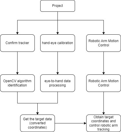
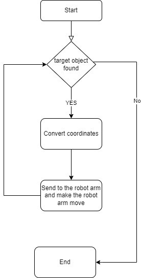
The following image is a flowchart of the project development process.
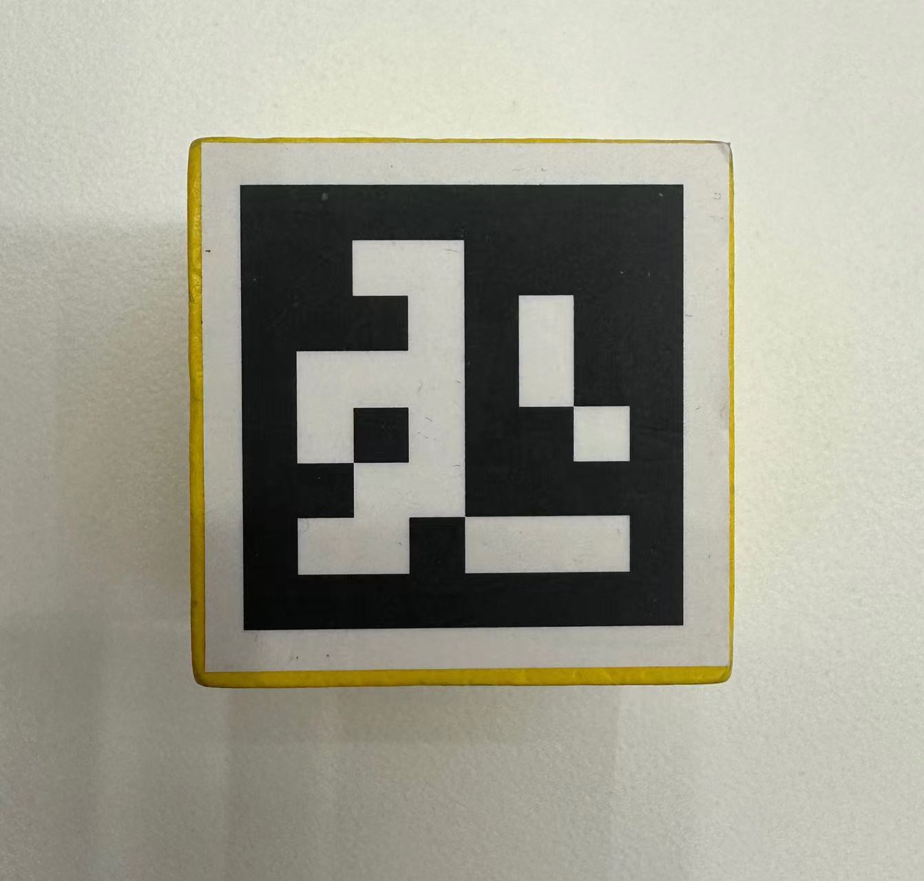
Capture the target
Before beginning development, we conducted some research and experiments. We used a camera to capture images of objects and utilized the OpenCV library for recognition. We attempted various methods, but object recognition required machine learning for the target we wanted to identify, which would increase the project development time. Ultimately, we decided to use aruco codes for identification, which allowed us to quickly capture the aruco codes and proceed to the next stage of development.
Code:def show_video_v2(self): # self.robot.init_robot() xyz = np.array([0,0,0]) LIST = [] num_count = 0 list_len = 5 # cmax = [180, 80, 240] # cmin = [130, -80, 200] cmax = [150, -150, 300] cmin = [-150, -250, 200] while cv2.waitKey(1) < 0: success, img = self.cap.read() if not success: print("It seems that the image cannot be acquired correctly.") break # transfrom the img to model of gray gray = cv2.cvtColor(img, cv2.COLOR_BGR2GRAY) # Detect ArUco marker. corners, ids, rejectImaPoint = cv2.aruco.detectMarkers( gray, self.aruco_dict, parameters=self.aruco_params ) if len(corners) > 0: if ids is not None: # get informations of aruco ret = cv2.aruco.estimatePoseSingleMarkers( # '''https://stackoverflow.com/questions/53303730/what-is-the-value-for-markerlength-in-aruco-estimateposesinglemarkers''' corners, 0.025, self.camera_matrix, self.dist_coeffs ) # rvec:rotation offset,tvec:translation deviator (rvec, tvec) = (ret[0], ret[1]) (rvec - tvec).any() xyz = tvec[0, 0, :] * 1000 rpy = rvec[0,0,:] camera = np.array([xyz[0], xyz[1], xyz[2]]) if num_count > list_len: target = model_track(camera) print("target", target) for i in range(3): if target[i] > cmax[i]: target[i] = cmax[i] if target[i] < cmin[i]: target[i] = cmin[i] pose = np.array([-103, 8.9, -164]) coord = np.concatenate((target.copy(), pose), axis=0) # q1 = math.atan(xyz[0] / xyz[2])*180/np.pi mc.send_coords(coord,50,0) # print('target', coord) num_count = 1 else: num_count = num_count + 1 for i in range(rvec.shape[0]): # draw the aruco on img cv2.aruco.drawDetectedMarkers(img, corners) cv2.imshow("show_video", img)Hand-eye calibration
Hand-eye calibration refers to the process of determining the position and orientation of the robot end effector (such as a mechanical arm) relative to the robot base coordinate system in the field of robotics. This process involves pairing the robot end effector with a camera and then determining its position and orientation in the robot base coordinate system by capturing its position and orientation in the camera's field of view.
Hand-eye calibration typically involves a series of movements between the robot end effector and the camera to collect enough data to calculate the transformation matrix between them. This transformation matrix describes the position and orientation of the robot end effector relative to the camera, which can be used to control the robot's motion and accurately perform the required tasks.
In "eye-to-hand" hand-eye calibration, the camera is considered a stationary observer ("eye"), while the robot end effector is considered a moving object in the camera's field of view ("hand"). As the robot end effector moves around the camera, a series of images are collected that contain information about the end effector's position and orientation at different locations and orientations. By analyzing these images, the position and orientation of the robot end effector relative to the camera can be calculated, completing the hand-eye calibration.
The following is the code for processing the coordinate transformation data.#The function is used to calculate the similarity between cameras. def calculate_similarity(camera): n = camera.shape[0] total_similarity = 0 for i in range(n): for j in range(i+1, n): vector_a = camera[i] vector_b = camera[j] dot_product = np.dot(vector_a, vector_b) norm_a = np.linalg.norm(vector_a) norm_b = np.linalg.norm(vector_b) similarity = dot_product / (norm_a * norm_b) total_similarity += similarity return total_similarity/n # The function is used to calculate the rate of change in similarity. def similarity_change_rate(new_similarity): global prev_similarity if prev_similarity is None: prev_similarity = new_similarity return 0 else: change_rate = (new_similarity - prev_similarity) / prev_similarity prev_similarity = new_similarity return change_rate #The function is used to convert a rotation matrix to Euler angles. def CvtRotationMatrixToEulerAngle(pdtRotationMatrix): pdtEulerAngle = np.zeros(3) pdtEulerAngle[2] = np.arctan2(pdtRotationMatrix[1, 0], pdtRotationMatrix[0, 0]) fCosRoll = np.cos(pdtEulerAngle[2]) fSinRoll = np.sin(pdtEulerAngle[2]) pdtEulerAngle[1] = np.arctan2(-pdtRotationMatrix[2, 0], (fCosRoll * pdtRotationMatrix[0, 0]) + (fSinRoll * pdtRotationMatrix[1, 0])) pdtEulerAngle[0] = np.arctan2((fSinRoll * pdtRotationMatrix[0, 2]) - (fCosRoll * pdtRotationMatrix[1, 2]), (-fSinRoll * pdtRotationMatrix[0, 1]) + (fCosRoll * pdtRotationMatrix[1, 1])) return pdtEulerAngle # The function is used to convert Euler angles to a rotation matrix. def CvtEulerAngleToRotationMatrix(ptrEulerAngle): ptrSinAngle = np.sin(ptrEulerAngle) ptrCosAngle = np.cos(ptrEulerAngle) ptrRotationMatrix = np.zeros((3, 3)) ptrRotationMatrix[0, 0] = ptrCosAngle[2] * ptrCosAngle[1] ptrRotationMatrix[0, 1] = ptrCosAngle[2] * ptrSinAngle[1] * ptrSinAngle[0] - ptrSinAngle[2] * ptrCosAngle[0] ptrRotationMatrix[0, 2] = ptrCosAngle[2] * ptrSinAngle[1] * ptrCosAngle[0] + ptrSinAngle[2] * ptrSinAngle[0] ptrRotationMatrix[1, 0] = ptrSinAngle[2] * ptrCosAngle[1] ptrRotationMatrix[1, 1] = ptrSinAngle[2] * ptrSinAngle[1] * ptrSinAngle[0] + ptrCosAngle[2] * ptrCosAngle[0] ptrRotationMatrix[1, 2] = ptrSinAngle[2] * ptrSinAngle[1] * ptrCosAngle[0] - ptrCosAngle[2] * ptrSinAngle[0] ptrRotationMatrix[2, 0] = -ptrSinAngle[1] ptrRotationMatrix[2, 1] = ptrCosAngle[1] * ptrSinAngle[0] ptrRotationMatrix[2, 2] = ptrCosAngle[1] * ptrCosAngle[0] return ptrRotationMatrixRobotic Arm Control
After this step, object detection and control of the mechanical arm follow, which involves converting the coordinates of the recognized object into motion commands for the mechanical arm. The pymycobot library is used to control the mechanical arm.
#The function is used for visual tracking and calculating the target position.
def Visual_tracking280(coord, camera):
    pose_camera = camera[:3]
    angle_camear = camera[3:]
    r = CvtEulerAngleToRotationMatrix(angle_camear)
    # r = np.array([[1, 0, 0],
    #                  [0, 1, 0],
    #                  [0, 0, 1]])
    euler = np.radians(coord[3:])
    R = CvtEulerAngleToRotationMatrix(euler)
    offset = np.array([0, 0, -250])
    Roff = np.array([[1, 0, 0],
                     [0, -1, 0],
                     [0, 0, -1]])
    # Roff = np.array([[1, 0, 0],
    #                  [0, 1, 0],
    #                  [0, 0, 1]])
    vector = pose_camera + offset
    # print("R", R)
    # print("r", r)

    move_pos = np.dot(np.dot(R, r), Roff).dot(vector)
    pos = coord[:3] + move_pos
    # angle = np.array(CvtRotationMatrixToEulerAngle(np.dot(np.dot(R, r), Roff))) * 180/np.pi
    angle =  coord[3:]
    target = np.concatenate((pos, angle))
    return target

    #Calculate the target position based on the camera coordinates.
def model_track(camera):
    model_pos = np.array([-camera[0], -camera[2], -camera[1]])
    camera_pos = np.array([-37.5, 416.6, 322.9])
    target_pos = model_pos + camera_pos
    # print("model_pos", model_pos)
    # print("target_pos", target_pos)
    return target_pos
Finally, let's summarize the logical relationship of the project.
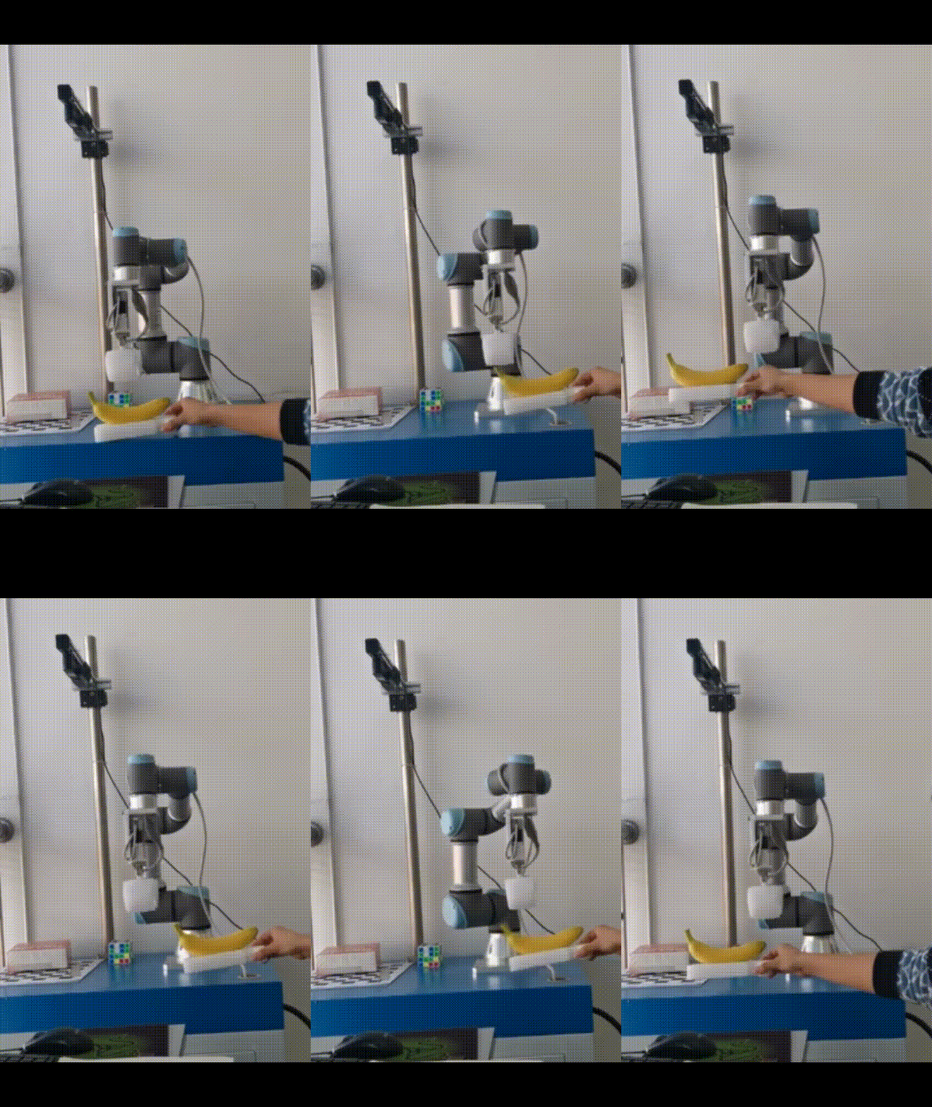
Let's take a look at how it performs.
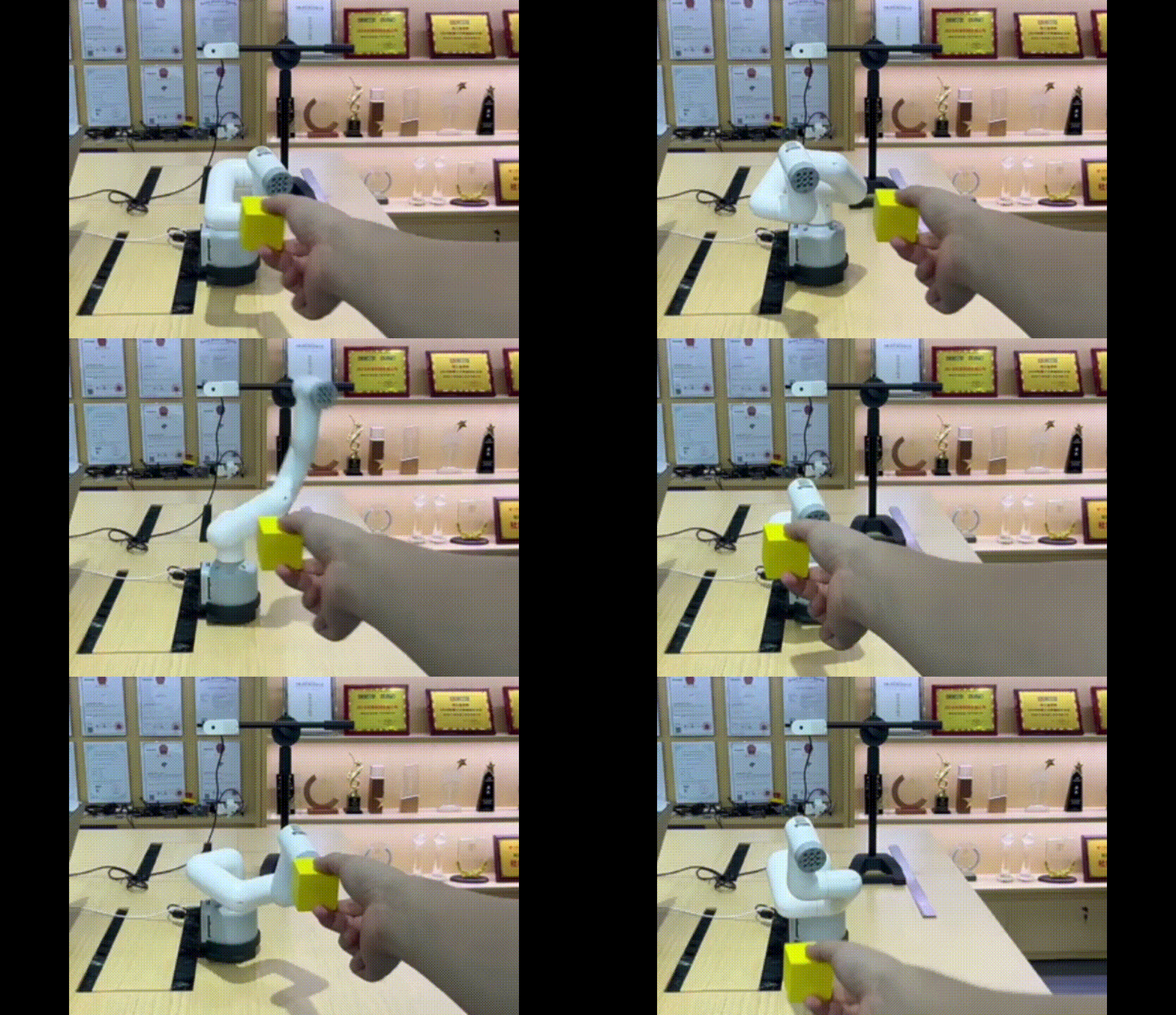
It may be noticed that sometimes myCobot does not move. This is because its body was blocking the camera, preventing it from capturing the target object. When moving objects, it is important to ensure that the mechanical arm body does not block the camera.This code is applicable to the entire myCobot280 series, including Pi, Jetson Nano, and other versions. The parameters may need to be adjusted based on the specific version being used.
People often compare the Jetson Nano with the Raspberry Pi. I have tried this program on two different robotic arms, and it is evident that the Jetson Nano version is much more responsive than the Raspberry Pi, owing to its superior computational power.There is a noticeable delay of approximately one second between them as observed by the naked eye.
Summary
During the debugging process, we found that the tracking effect was not very smooth and responsive. We adjusted the smoothness by controlling the detection cycle, but it was necessary to slowly move the tracked object to achieve better results. There are still some shortcomings, as the body of the mechanical arm may block the camera's field of view when the camera is fixed, making it impossible to proceed with the next tracking step. One solution we thought of is to move the camera to a position where it is not blocked (which would require recalculating the coordinates). If you have any better ideas, please feel free to communicate with us! Thank you for your patience.