RFID. How to reach maximum distance?
-

Hello. I'm using RFID U107 (or JRD-4035 - I don't know how it's properly called) for my project.
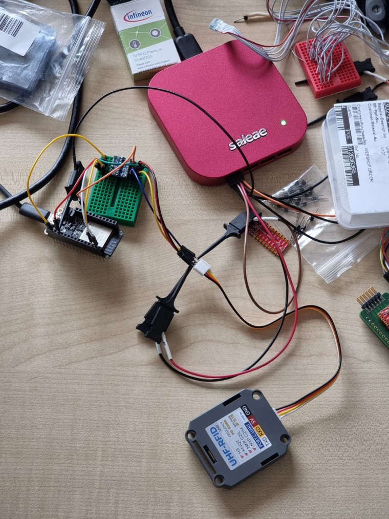
My setup includes RFID, Adafruit ESP32 Feather and a board that transforms 5V-logic to 3,3V-logic (and vice versa).
In the description for RFID is noticed that the distance for recognition is up to 1.5-2 meters, but in my case it's up to 30-50 cm. Can you help and explain how to reach the distance of 1.5-2 m, please?For my work I use an example from here: https://github.com/m5stack/M5-ProductExampleCodes/tree/master/Unit/UHF_RFID
I tried to change transmitting power to its maximum by using a function "Set_transmission_Power" and found that the maximum power is 2600 by reading set value with a function "Read_transmitting_power". So I'm using "Set_transmission_Power(2600)" at the moment.
Also I tried to change "Region" to EU, but this function ("Set_up_work_area(3)") doesn't work. I read this value after configuration and it is "1" (CH). I don't know if this is important. If it can do working distance larger I can try to find why this function doesn't work as expected.
And I found the function "Sets_the_receiv_demodulator_parameters" but don't know what parameters I should use to set maximum working distance.
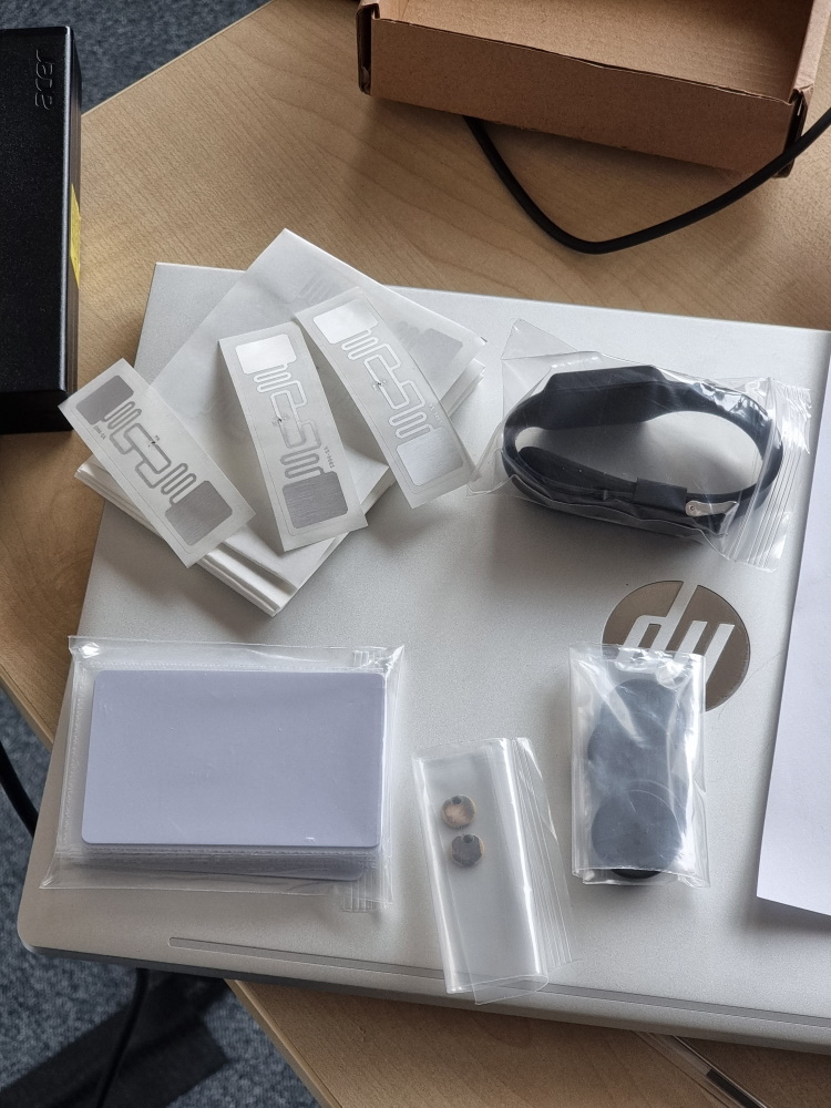
I have a set of different tags and of course the bigger tag is the larger the recognition distance I get. If the problem is in tags size what tags do you recommend?My setup code:
void setup()
{
  Serial.begin(115200);
  Serial.println("Program started!");
  Serial1.begin(115200, SERIAL_8N1, SERIAL1_RXPIN, SERIAL1_TXPIN);
  Serial.println("Second Serial activated!");

  RFID._debug = 1;

// UHF_RFID set UHF_RFID设置
  Serial.println(RFID.Set_transmission_Power(2600));
  delay(100);
  delay(100);
  Serial.println(RFID.Set_up_work_area(3));
  delay(100);
  ReadInfo transmissionPower = RFID.Read_transmitting_power();
  Serial.print("Pow: "); Serial.println(transmissionPower.Pow);
  delay(100);
  transmissionPower = RFID.Read_working_area();
  Serial.print("Region: "); Serial.println(transmissionPower.Region);
  Serial.println(RFID.Set_the_Select_mode());
  RFID.Delay(100);
  RFID.Readcallback();
  RFID.clean_data();

// Prompted to connect to UHF_RFID 提示连接UHF_RFID
  Serial.println("Please connect UHF_RFID to Port C");

// Determined whether to connect to UHF_RFID 判断是否连接UHF_RFID
  String soft_version;
  soft_version = RFID.Query_software_version();
  while(soft_version.indexOf("V2.3.5") == -1)
  {
    RFID.clean_data();
    Serial.println("Waiting...");
    RFID.Delay(150);
    Serial.println("Waiting...");
    RFID.Delay(150);
    soft_version = RFID.Query_software_version();
  }

  Serial.println("Please approach the RFID card you need to use");
  Serial.print("Software version: "); Serial.println(soft_version);

}
To summarize my questions are:
- The maximum transmission power is 2600?
- Is the "Region" important for the recognition distance? The same question to the working channel because I don't set it.
- What parameters should I use for the function "Sets_the_receiv_demodulator_parameters" if I want to reach the maximum distance?
- How I can reach the maximum distance of 1.5-2 meters (thanks for any advice)?
- Can I find something like a datasheet for this RFID unit because the description I see on the product page isn't enough to understand how it works and how properly to work with it?
-
@oleksii
What tags are you using?
What reading distance can you currently archive? -
Hello,
I begin with this RFID UHF reader (U107), and i encountered the same issue to solve, i.e. to optimize the read distance when "Europe work location" is selected.
The patch antenna within the U107 seems fitted to 900MHz band, and as this antenna is very small therefore the bandwith is really narrow. The read performance at 868MHz are then degraded.
The solution I found is to modify the patch antenna like this: you have to remove the box to access the top of the patch antenna, and you have to remove the white adhesive protective sheet and stick in place a square of aluminiun adhesive tape above/againts the roof of the integrated patch antenna.
The size of about 30mm by 30mm seems close to the best ... but you can try other sizes and see. You can also try cropping the opposite angle along the diagonal passing between the two feed points (not a lot !).
Best regards,
Thierry -
Hi,
About change "region":
I implement the reader U107 (JRD-4035) with an USB to serial TTL UART interface (a TTL-232R-5V-PCB fron FTDI Chip) and can drive this reader with a serial terminal software as RealTerm (that supports frame of hex bytes) for simple tests (with Pyserial for a more evolved application).
Then it is possible to check active "region" parameter, by send the command frame: 0xBB 0x00 0x08 0x00 0x00 0x08 0x7E. After a power On, the response is: BB 01 08 00 01 01 0B 7E corresponding to "China 900MHz" (01).
We have to send the command: 0xBB 0x00 0x07 0x00 0x01 0x03 0x0B 0x7E to pass in "EU region", the reponse after the command: 0xBB 0x00 0x08 0x00 0x00 0x08 0x7E, is BB 01 08 00 01 03 0D 7E region parameter has well switched to "EU region" (03).
(note: if the USB dongle is unplugged then plugged, the region parameter returns to '01')About documentation on this reader: I used this manual "https://m5stack.oss-cn-shenzhen.aliyuncs.com/resource/docs/datasheet/unit/uhf_rfid/MagicRF M100%26QM100_Firmware_manual_cn.pdf" and "translate Google tool" (the en version of the manual is not sufficient).
Best,
ThierryPS: the link between U107 and the FTDI interface module is: TXD/U107 to RXD/FTDI, RXD/U107 to TXD/FTDI, 5V to VCC and GND to GND.