m5stack camera module - hardware design bug
-
We have tested 7 m5stack camera modules we have bought from a vendor at AliExpress.
We see an odd behaviour sometimes they work, sometimes not, some show image artefacts some do not even start AP.
Digging deeper we probably found the cause and this is what we also found on Espressif Wroverkit as a real bug – there are no pullup resistors on the I2C bus !!!
The GPIOs for SDA/SCL are programmed as open collector with internal pullup but this is much too weak for I2C bus.
This has also been posted already in the ESP32 forum, it is absolutely necessary to have pullups (<= 10k) on SDA and SCL.Looking into the schematics of m5stack camera module. I2C signals SIO_D and SIO_C are connected to GPIO25 and GPIO23 respectively (Pin3 and Pin5 of the FPC connector). You can see in the schematics that these GPIOs are connected to
the ESP32 (Pin 36 and Pin14) but do not have a pullup resistor.If you are running I2C only with weak internal pullup of ESP32 you will have a very unreliable system, if you are lucky the OV2640 get setup but maybe some bytes are not transmitted correctly. And this is exactly what we see, sometimes it is working (but with issues) sometimes not at all.
As there is no rework possible m5stack should consider to do a new harware revision
-
I was thinking about buying the m5stack camera module, but if this is the case, it makes it almost unusable.
Anyone can confirm this is the case on their hardware too, and it's not an old batch? -
The "Uncased" model is useless, the psram version is far better.
@hg wait a few months as a new version of the camera is on its way.
-
I think they are not using pullups for I2C in their other products too and this is a general bug in M5Stack hardware.
-
As far as I am aware (from studying the docs) The Camera doesn't use I2C (hence the current lack of need for the pullups on the internal i2c bus. From what I read, the camera uses the quicker SPI interface.
-
@ajb2k3
This is not true.
The M5Stack ESP32 Camera Module is using a OV2640 with a "hack" of the I2S interface because this ESP32 subsystem is able to DMA for the data. The camera control is over the Serial Camera Control Bus (SCCB) protocol that is using I2C routines. Additionally the GROVE connector makes the I2C accessible for peripherals.
The M5Stack ESP32 WROVER with PSRAM Camera Module additionally has the BME280 and MPU6050 on a second I2C.But who knows? Still there are no up to date schematics. I mean something with the actual wiring of the PCB. Not the overview picture. Which is btw only posted on Aliexpress:

My opinion: It is a silly idea to share the camera VSYNC and SIOC with the BME280 and MPU6050.
-
@playthegame 在 m5stack camera module - hardware design bug 中说:
@ajb2k3
This is not true.
The M5Stack ESP32 Camera Module is using a OV2640 with a "hack" of the I2S interface because this ESP32 subsystem is able to DMA for the data. The camera control is over the Serial Camera Control Bus (SCCB) protocol that is using I2C routines. Additionally the GROVE connector makes the I2C accessible for peripherals.
The M5Stack ESP32 WROVER with PSRAM Camera Module additionally has the BME280 and MPU6050 on a second I2C.But who knows? Still there are no up to date schematics. I mean something with the actual wiring of the PCB. Not the overview picture. Which is btw only posted on Aliexpress:
My opinion: It is a silly idea to share the camera VSYNC and SIOC with the BME280 and MPU6050.
Actually it does not have the BME and MPU (I have had this convo with m5stack and dissasembled it.
The MPU version is on its way!
The Grove is on a seperate I2C bus.Ahhh I see, Buy hacing the I2S bus you gain the full duplex needed for the camera along with the other lines which allow you to use the same clock line but seperate data lines.
@playthegame Cool didn't know that as Just been concentrating on running the two I2C buses.
@M5Stack, can we get some clear up here over the configuration? -
Just updated my pins_arduino.h file for the M5Camera.
https://github.com/Ajb2k3/M5Drone/blob/master/pins_arduino.hCan someone double check this please as I haven't listed I2S yet.
-
Well, because of lack of documentation you are on your own.
The demo example lists
Pin Configuration
CONFIG_D0=32
CONFIG_D1=35
CONFIG_D2=34
CONFIG_D3=5
CONFIG_D4=39
CONFIG_D5=18
CONFIG_D6=36
CONFIG_D7=19
CONFIG_XCLK=27
CONFIG_PCLK=21
CONFIG_VSYNC=22
CONFIG_HREF=26
CONFIG_SDA=25
CONFIG_SCL=23
CONFIG_RESET=15The big question is: Is the BME280 and MPU6050 soldered on the board (as you indicated)? Is the I2C SDA of the BME280 physically connected to G22 as the leaflet says or G25?
For me unsoldered peripherals is very suspicious. It smells like big hardware bug. If M5Camera with PSRAM based on WROVER module uses really G22 for the I2C and also connects this pin as VSYNC to the cam the bug is obvious.
A proper design is with I2C pullups. Here is an example from bitluni
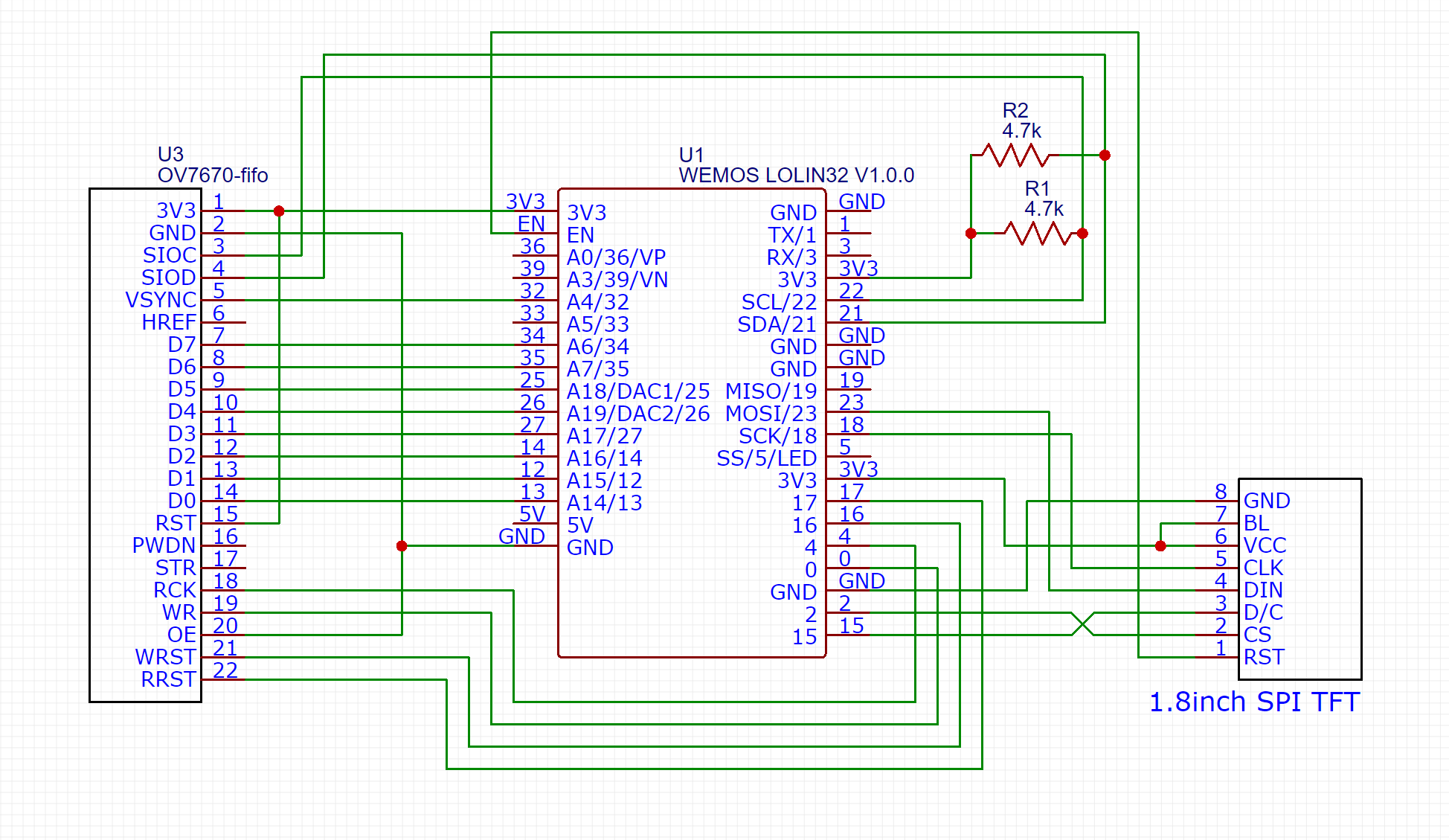
-
@playthegame "Unsoldered Peripherals" are classed as optional extras but I see where you are going with the pullups.
Didn't know about Bitluni so currently scouring his work.
Hello! It looks like you're interested in this conversation, but you don't have an account yet.
Getting fed up of having to scroll through the same posts each visit? When you register for an account, you'll always come back to exactly where you were before, and choose to be notified of new replies (either via email, or push notification). You'll also be able to save bookmarks and upvote posts to show your appreciation to other community members.
With your input, this post could be even better 💗
Register Login