-
Hi!
M5STACK-FIRE with 3 DS18B20 1-Wire-Temperature-Sensors connected to Grove B connector (GPIO26) and appropriate Software works perfect and the software reads and displays the 3 temperatures.
As soon as I connect 1 additional sensor to the 3 sensors, the software does not detect any of the sensors.
I have a total of 5 sensors and all of them are ok. It does not matter which 3 of the 5 sensors are used, everything works fine, as long as I don't connect an additional sensor.
Each sensor has a 1 meter cable and yes, the 4,7 kohm resistor is installed between data-wire and +5V (from Grove B connector).
Measured with a oscilloscope:- the +5V voltage stays constant at +5V
- the data-line switches between 0V and 3,8V (3 sensors connected and system works)
- the data-line switches to 0V (for 480 microseconds) and than to 2,0V (4 sensors connected and system does not work)
Is there anything I have to take care of to use more than 3 DS18B20 on a 1-wire-bus?
Would it help, if the value of the pull-up resistor ist reduced? What is the minimum allowed value? -
@grelm I don't think anyone here knows the answer to this question as I think that you are the only one testing them. Have you tried asking on the suppliers community?
If you solve this problem, please come back and let us know the solution.Please and Thank you
AJB2K3. -
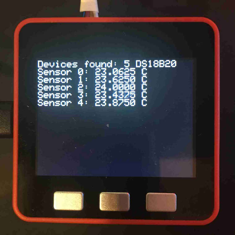
After reading thru data sheets and application notes I took the risk and use a 2 kohm resistor instead of a 4, 7kohm resistor (as almost everywhere recommendd).
Now all 5 DS18B20 are detectable and readable by the software.
By the way: signal low level <= 0,2V, signal high level => 3,5 V, signal slopes are much "nicer".
I will now continue with my project: total of 10 x DS18B20 and cable length of about 10 and 20 meters.
I will keep you informed of the results. -
@grelm Please do.
Can you create a github and upload pictures and code to it?
Can you also create a project to share your progress as I am now curious as to what your project is doing. -
@ajb2k3 Sorry, up to now I do not know how to to create a "github" and a "project" - I will need to do some "learning" on that.
In the meantime I am giving you some information in this forum:
The planned project:
Logging of data of the house heating system for "years" for diagnostical and statistical purposesFunctions needed in detail:
- measuring of about 10 temprature sensors, environmant data, oil burner run time, +++
- getting date and time from webserver via WLAN
- use buttons for start/stop of measurement, single measurement, +++
- show actual data on Lcd of M5Stack and monitor (if connected)
- write all data to SD-card
- use LED's of M5Stack-Fire for heartbeat, measurement in progress, waiting for next measurement slot, WLAN connection, +++
- optional: sending data to PC via WLAN to import them into Excel for analysis (or transfering the data from SD-card to PC via a card-reader)
- optional:Webserver for live-data and SD-card-data
- +++, tbd
... puh..., I fear, this will be long way to go (at least for me...).
The software (up to now, this is all I have so far - I wanted to start with testing and building up some experiences of using the DS18B20 sensors connected to a M5Stack-Fire):
/* * Software for basic tests of temperature measurement on M5Stack-FIRE with several DS18B20 temperature sensors * 1-wire-pull-up resistor = 2 kohm (did not not work with 4,7 kohm !!!! * modified by GRELM; 2019-06-16 */ #include <M5Stack.h> #include <OneWire.h> #include <DallasTemperature.h> #define ONE_WIRE_BUS 26 //DS18B20 on Grove B corresponds to GPIO26 on ESP32 OneWire oneWire(ONE_WIRE_BUS); DallasTemperature DS18B20(&oneWire); /* Resolution of DS18B20 temperatur measurement = power-on-default = 12 bit = 0.0625 C *9-bit resolution --> 93.75 ms *10-bit resolution --> 187.5 ms *11-bit resolution --> 375 ms *12-bit resolution --> 750 ms */ String monitorstring = ""; void setup() { M5.begin(); M5.Lcd.setTextColor(TFT_WHITE,TFT_BLACK); M5.Lcd.setTextSize(2); M5.Lcd.clear(); //just to make sure... Serial.println(); // to separate data from booting output monitorstring = "Date;Time;A;B;C;D;E;F;G;H;I;J;"; // up to 10 data-colums fpr up to 10 sensors Serial.println(monitorstring); // Monitor Headline for Excel Headline } void loop() { float celsius; float fahrenheit; monitorstring = "Date;Time"; // change to realtime date and time of M5Stack (later) DS18B20.begin(); int count = DS18B20.getDS18Count(); //check for number of connected sensors // M5.Lcd.clear(); //clearing causes flickering of Lcd-display, looks nicer without M5.Lcd.setCursor(0,0); M5.Lcd.print("Devices found: "); M5.Lcd.print(count); M5.Lcd.println(" DS18B20"); if (count > 0) { DS18B20.requestTemperatures(); for (int i=0; i < count; i++) { String m5stackstring = "Sensor "; celsius = DS18B20.getTempCByIndex(i); m5stackstring = m5stackstring + String(i) + String(": ") + String(celsius,4) + String(" C "); M5.Lcd.println(m5stackstring); // 1 line per sensor on M5Stack Lcd monitorstring = monitorstring + String(";") + String(celsius,4); // ";" is Excel compatibel separator } Serial.println(monitorstring); // 1 line for all measurements on serial monitor } delay(500); //Measuremnt interval } -
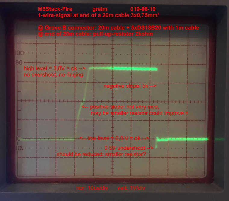
FYI: Update on hardware configuration, 2019-06-18:
There is now a 20 meter long cable between the M5stack (Grove B) and the 5 DS18B20 (each with 1 meter cable).
The software still works fine as before: it detects all 5 sensores and displays the temperature values on the M5Stick Lcd.NB: The used cable is a YM-L3G 0,75mm2 installation cable. I know, it is much to massive for the signal current, but it is easier and more robust for later installation.
-
@grelm Check the volt drop on each end of the cable. When I connected my shed lights to the solar panels it was something I had to check.
Nice work so far, any chance of some photo's?
-
Measuremnts of supply-voltage and signal-shape:
- Voltage of +5V-line: +5,07 V at Grove-connector and at end of 20m-cable = ok = no voltage drop (measured with DMM)
- Signal-shape of 1-wire-signal-line: see attached photo below = ok, but seee comments in photo (measured with oscilloscope Sony/Tektronix 335)
-
@grelm Hello can you show how you have connected ds18b20 to jack and jack to grove please ?
-
@saiaman01 What exactly do you want to know or see?
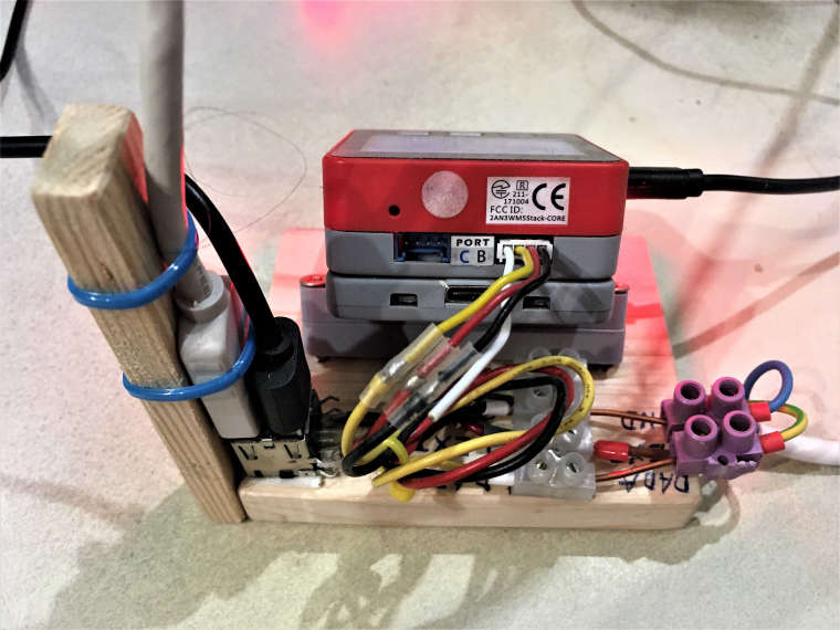
May be the two pictures are of help to you.
Or do you need a schematic or any explanation?Picture 1
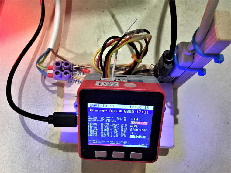
Picture 2
Hello! It looks like you're interested in this conversation, but you don't have an account yet.
Getting fed up of having to scroll through the same posts each visit? When you register for an account, you'll always come back to exactly where you were before, and choose to be notified of new replies (either via email, or push notification). You'll also be able to save bookmarks and upvote posts to show your appreciation to other community members.
With your input, this post could be even better 💗
Register Login